


DATALOGIC S.p.A.
Via Candini 2
40012 - Lippo di Calderara di Reno
Bologna - Italy
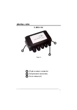
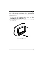
C-BOX 100
Ed.: 09/2003
ALL RIGHTS RESERVED
Datalogic S.p.A. reserves the right to make modifications and improvements without prior notification.
Datalogic shall not be liable for technical or editorial errors or omissions contained herein, nor for incidental or
consequential damages resulting from the use of this material.
Product names mentioned herein are for identification purposes only and may be trademarks and or
registered trademarks of their respective companies.
Datalogic S.p.A. 2001 - 2003
821000552 (Rev. B)
Содержание C-BOX 100
Страница 1: ...C BOX 100 Installation Manual...
Страница 2: ...C BOX 100 Installation Manual...
Страница 3: ...C BOX 100 INSTALLATION MANUAL...
Страница 10: ...viii...


