background image


 Instruction 

Manual 


DataVS1 

Series  


55 


The sensor now behaves as required. As the result is satisfying, press 

STATUS

 again and move 

on to defining the behaviour of the outputs. 


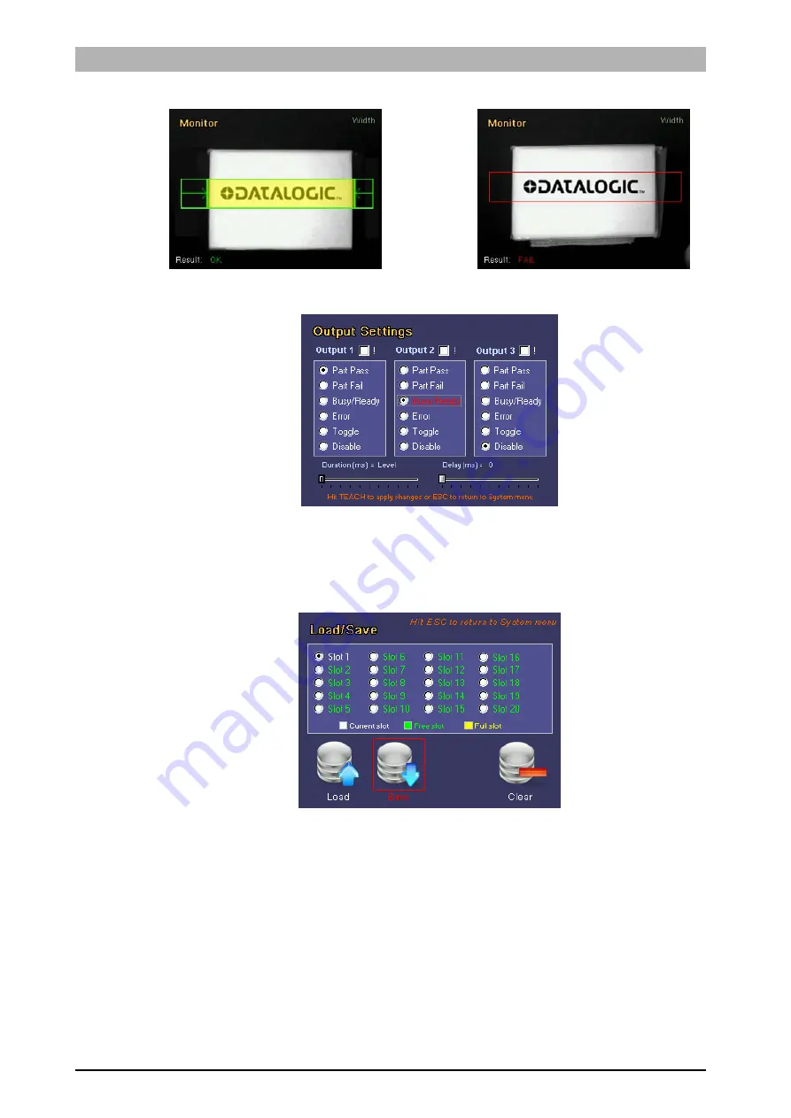
Let's associate output 1 to the Part Pass behaviour and output 2 to the Busy/Ready behaviour. 
Press 

TEACH

 to save the modifications. 

 
Now let's save the bank on the sensor. Enter the Bankset menu and save the inspection in 
memory bank 1. 


Press the 

ESC

 button to return to Monitor mode. 


Содержание 959941000

Страница 1: ...Smart Vision Sensor INSTRUCTION MANUAL ...

Страница 2: ...logic com e mail info automation it datalogic com DATALOGIC AUTOMATION reserves the right to make modifications and improvements without prior notification Datalogic and the Datalogic logo are registered trademarks of Datalogic S p A in many countries including the U S A and the E U 826003842 rev B Copyright Datalogic 2009 2010 ...

Страница 3: ......

Страница 4: ...s and saving the inspection settings to the sensor 23 6 VSC CONFIGURATOR ADVANCED FUNCTIONS 26 6 1 Output 26 6 2 Trigger Mode 28 6 3 Load Save 30 6 4 Fail Inspector 32 6 5 DataVS1 Ver 33 6 6 Input Config 34 6 6 1 Standard Protocol 34 Protocol description 34 Protocol selection 35 Inspection switch timing 35 6 6 2 Expert Protocol 36 Protocol Description 36 Protocol Selection 38 6 6 3 Digital Teach I...

Страница 5: ...eral description DataVS1 by Datalogic is a vision sensor machine vision which is easy to use and has advanced inspection functions which allow it to be implemented in many fields quality control on production lines or automatic material handling are just a few examples It basically works by comparing the digital image acquired in a precise moment target image and a previously acquired reference im...

Страница 6: ...pin 8 GROUND M12 8 poles power and I O pin 1 white digital input 1 pin 2 brown 24 Vdc pin 3 green STROBE for external illuminator pin 4 yellow output 1 pin 5 grey output 2 pin 6 pink output 3 pin 7 blue GROUND pin 8 red external trigger VSC Configurator M12 8 pole Ethernet DataVS1 connection pin 1 ethernet TX pin 2 ethernet RX pin 3 ethernet RX pin 4 not used pin 5 24 Vdc pin 6 not used pin 7 ethe...

Страница 7: ...S1 08 DC x DataVS1 06 DC S 50 17 x 12 25x20 42x30 80 25 x 20 40x30 60x41 110 33 x 25 55x40 80x55 140 31 x 24 45 x 35 70x50 98x69 170 39 x 29 53 x 38 85x60 118x83 200 46 x 34 60 x 50 100x70 138x92 300 70 x 53 90 x 65 145x103 201x140 400 94 x 71 121 x 82 186x132 265x189 500 118 x 89 150 x 110 236x167 330x232 600 143 x 107 185 x 130 282x232 385x270 ...

Страница 8: ...nsor can therefore function in a stand alone mode and automatically acquires an image controls it and then activates the outputs according to the result of the inspection The images seen below highlight the main characteristics of the sensor The user interface is also inserted in the upper part of the sensor consisting in 4 LED indicators and a Teach in button More precisely LED 1 Power green SELE...

Страница 9: ...e which allows it to focus and observe the entire target object to be inspected Resolution On the contrary to the field range dimension concept the resolution of the image acquired by the sensor decreases as the distance from the target object increases This is because the sensor acquires an image with 640x480 pixels Increasing the focus range decreases the number of pixels per unit The image to t...

Страница 10: ...to vibrations and protected from contact with any liquids The catalogue stocks a range of brackets which are specifically designed to support the sensor For instance the diagram below shows a sensor fitted with an assembly kit 95A901380 The VSC configurator is an excellent instrument used to find the best position for the sensor It allows the installer to view the field range of the DataVS1 in rea...

Страница 11: ...dification of parameters from the viewing of the results and statistics to the management of digital outputs Once the DataVS1 settings have been completed the configurator can be used to view the results of the current target inspection or it can be disconnected so that the sensor will continue to function in stand alone mode The image seen below highlights the main characteristics of the VSC see ...

Страница 12: ... the device to a DIN Rail During installation it is therefore sufficient to wedge the configurator on the rail and block it in place using the two white locking clips It is also possible to install the VSC configuratore on a panel All the accessories for this kind of installation are included in the package DIN Rail Locking clips Slot for the DIN Rail ...

Страница 13: ... DataVS1 Series 9 First place the rubber seal around the body of the configurator paying attention to the shape of it Then fix the configurator to the panel by using the two locking screws and the rubber caps Rubber seal ...

Страница 14: ... Hardware connections Connect the power and I O cable CS A1 06 B xx inserting it into the connector identified by the PWR I O icon Connect DataVS1 to the VSC using the relative connection cable SVS CV VSC xx PWR I O Locking screws Rubber caps ...

Страница 15: ... installing the sensor and configurator Make sure that the product is suitable for the system that you intend to set up Connect the cables to the devices with the poles in the right direction Power up the devices following the instructions contained in the Manual Protect all devices against dust dirt and humidity Never spill liquids on the devices It is strictly prohibited to use DataVS1 on system...

Страница 16: ...he following diagram Example Press the Status button 5 2 VSC user interface The chart below provides a general overview of the user interface on the VSC configurator Please note however that the functions of the buttons vary according to the operating mode selected by the user Please consult the next chapters for further details on how the system reacts to the pressing of the buttons BUTTON ID but...

Страница 17: ...ilitate correct configuration Decide exactly which feature of the product must be monitored Make sure that the lighting is correct and above all as consistent as possible correct image acquisition is achieved by minimising the influence of the environmental light in the area being monitored Make sure there is good contrast between the object being monitored and the background Carefully choose the ...

Страница 18: ...reen Set Net LED will light up and the monitor will display the following image As you can see in the image the VSC screen is split into two main areas the field range of the camera and the settings and options available The image acquired by the sensor is displayed in the first area If the field is out of focus it is possible to adjust the focus ring on the sensor see par 4 1 The configuration op...

Страница 19: ...ng blurred images where the detail being monitored moves at a certain speed If the images of objects that move quickly are not very bright it is recommended to adjust the gain settings To adjust the exposure time move to the option and use the RIGHT LEFT ARROW buttons Gain The gain setting allows you to adjust the brightness of the image acquired by the sensor by amplifying the signal transmitted ...

Страница 20: ...RROWS on the VISION TOOL icon and press the SET button Use the ARROW buttons to scroll the menu options Press the SET button to confirm the inspection tool to be used The chart given below provides a brief summary of the controls that can be selected Please refer to Chapter 7 for further information and details on the inspection tools Tool Icon Function Brightness Calculation of the average bright...

Страница 21: ...this defines the area within which the algorithm searches the edges on the detail of which it is necessary to measure the width Edge Counting This describes the area within which a search is made for edges which are then counted by the algorithm Pattern Match This defines the pattern detail to be searched within the whole focus range OCV This describes the portion in which the device searches for ...

Страница 22: ...possible to increase or decrease the ROI size using the ARROW buttons The size expressed in pixels of the current ROI are displayed at the bottom of the screen Once you have achieved the desired size press the TEACH button to save the settings and return to the Setup menu Press the ESC button to return to the Setup menu without saving the modifications the system will request confirmation on the s...

Страница 23: ... brief description of the same and the current values Settings are displayed one at a time To move from one setting to another use the LEFT RIGHT ARROW buttons To adjust the current setting use the UP DOWN ARROW buttons By pressing the button the value will increase decrease by one unit To modify the value faster press and hold the button The settings in this section vary according to the selected...

Страница 24: ...right hand corner ROI Inspection result bottom left hand corner Fail Mode LEFT ARROW The monitor displays the image of the last inspection which had negative fail result fault Zoom Mode RIGHT ARROW An image of the sensor field focus is displayed on the monitor with 200 zoom A rectangle in the bottom right hand corner indicates the position of the displayed area compared to the overall image and th...

Страница 25: ...mpressed along the x axis using a factor of 100 Press SET to exit the statistics mode If the results of the defined inspection are not as desired it is possible to press the ESC button to return to the previous configuration step Press once to return to the Adjust menu press twice to return to the Setup menu When you are satisfied with the results proceed to the fourth and final configuration step...

Страница 26: ... the VSC to a DataVS1 which is currently monitoring The device will switch to Monitor Mode and display the current sensor functions We then decide to increase the minimum acceptance threshold of the pattern match tool as sometimes the inspection does not provide the desired results We therefore press ESC to return to Adjust mode and press ARROW UP to increase the threshold We now return to Monitor...

Страница 27: ...ress ESC if you wish to return to Monitor mode 5 7 Step 4 Output definitions and saving the inspection settings to the sensor When you enter System Mode the VSC will display the following menu Before saving the inspection to the sensor it is necessary to set the digital outputs The sensor has three configurable digital outputs for each of these you can set the operating mode duration and delay dur...

Страница 28: ... output will take on value 1 on receiving the signal Error This indicates an error on the sensor Toggle The output will indicate alternately the logic values 1 and 0 each time it acquires and processes an image In this configuration there is no relation between the value indicated on the output and the result of the processed image Disable The output is disabled By default the three outputs have t...

Страница 29: ... confirm exit and ignore the modifications use the ARROWS to reach NO and press SET The configuration phase has been concluded when all the output settings have been completed Now you must render the modifications permanent and save the inspection to the sensor databank Select the LOAD SAVE option from the main menu and press the SET button It is possible to manage the sensor memory slots from the...

Страница 30: ...ive result If a failure occurs it remains low Part fail The output is enabled if a failure occurs If the control gives a positive result it remains disabled Busy Ready The output takes on value 1 Busy for the entire time the sensor takes to acquire and process the image The output takes on value 0 Ready when the sensor is ready to acquire a new image If the image is acquired under the control of a...

Страница 31: ...ameters are common to all the digital outputs and therefore it is not possible to set different values for different outputs Duration this indicates the length of time in ms the output must maintain the last acquired value this is mainly used for Part Present Part Pass and Part Fail modes Delay indicates after how long the output shall display the last acquired result It delays the time the output...

Страница 32: ...for processing To this purpose there are 3 trigger options available in the System menu Continuous Hardware Rising edge Hardware Falling edge Continuous trigger The acquisition of the image to be processed is performed at the fastest speed possible Each individual image is acquired and immediately processed as soon as the sensor is ready the next image is acquired and so on This type of trigger is...

Страница 33: ...ignal naturally has a rising and falling edge If the Rising Edge is selected the image acquisition signal follows the rising edge of the external device If the Falling Edge is selected the image acquisition signal follows the falling edge of the external device Image acquisition Control Measurement OK FAIL INSPECTION Photocell TRIGGER ...

Страница 34: ...he load save menu is the only access point to the FLASH memory installed on the sensor During all configuration steps in fact a RAM type memory is used which is reset each time the device is powered down Therefore when the current settings are modified and you wish to render them permanent it is necessary to save the inspection tool using the load save menu The 8 memory slots available on the sens...

Страница 35: ...o select the option using the ARROW buttons and then press SET to confirm Save this saves the current inspection to the selected bank Press the SET button to save the current inspection onto the device If the selected slot is not free a message will appear on the screen asking if you wish to overwrite the inspection currently saved in this databank Use the ARROW and SET buttons to scroll and selec...

Страница 36: ...creen Use the UP DOWN ARROWS to scroll the fail list Some information data is displayed on the right for the selected fail More precisely Label Description Tool Name of the current tool ROI X Co ord Value of the X co ordinate expressed in pixels from the top left hand corner of the ROI ROI Y Co ord Value of the Y co ordinate expressed in pixels from the top left hand corner of the ROI ROI width Wi...

Страница 37: ...HT ARROW and LEFT ARROW buttons To return to the main menu of the fail inspector press the ESC key 6 5 DataVS1 Ver From the DataVS1 Version control panel it is possible to check the software version currently loaded on the device and its release date To return to the main menu press the ESC key ...

Страница 38: ...ecuzione e comunicare al sensore il numero dello slot dell Ispezione da commutare PIN 4 Output 1 PIN 5 Output 2 PIN 6 Output 3 Fondamentalmente il prologo è composto da tre impulsi di durata 10 100 ms e un duty cicle del 50 Il primo impulso apre la finestra del prologo che ha una durata massima di Y X 6 delta ms dove X è la durata dell impulso selezionata e delta è un margine impostato come il 5 d...

Страница 39: ...m an Inspection teaching phase on the reference image before going in run mode a unique and definitive timing of the inspection change process is not available because it will depend on the inspection time itself If the inspection use very fast tools for example Position or Width it will be quite fast hundred of milliseconds if the inspection is quite slow for example a difficult pattern match the...

Страница 40: ...switching request As a reaction the sensor sets all outputs to LOW Note in the worst case the time interval occurring between the instant when the Select Inputs signal arrives to the sensor and the instant when the sensor set outputs to LOW can vary depending on the current running Inspection After receiving the Select Input signal the sensor will finish the current Inspection cycle and then will ...

Страница 41: ...igger Input HIGH Sensor MSB ACKNOWLWDGE BITS The second Trigger Input pulse after phase 5 activates the Inspection selection acknowledge The sensor sets its outputs in order to represent the MSB Most Significant Bits of the binary coding of the Inspection selection number where output 1 represents the LSB of the first 3 bits and output 3 represents the MSB of the first three bits Example o Inspect...

Страница 42: ...e Image and perform a new Teach phase on the current running Inspection Note the sensor will not send any acknowledge to the digital Teach In request To enable digital Teach In function through just select one of the following options from Input Pin setup menu Tach only digital teach in will be enabled Advanced Inspection Selection Ptotocol Teach both digital teach In and Advanced Inspection Switc...

Страница 43: ... operations Modify the password To modify the current password select the Modify option and then press SET to confirm The device will request the user to enter the current password first Once the old password has been entered a new one can be entered too Disabling the password To disable the password option select the Disable option and then press SET to confirm The device will request the user to...

Страница 44: ...assword the user can go to the other configuration panels in which it is possible to change the parameter settings After 5 minutes without changes the device goes back to monitor mode and it enables the password again If the password is lost insert the unlock code STATUS STATUS STATUS STATUS TEACH TEACH TEACH STATUS STATUS TEACH This sequence will unlock the sensor and disable the password ...

Страница 45: ...he top left corner of the work area Each inspection tool is analysed below highlighting the Description control functions Selection indication of the menu from which it can be selected Positioning ROI positioning and resizing procedures Parameters description of the configuration parameters Result description of the achieved result Example here is a complete example from selection to configuration...

Страница 46: ...ield range To modify the position of the ROI move to the Move ROI icon and then press SET It is now possible to move the ROI using the ARROW buttons Once you have achieved the desired position press the TEACH button to return to the Setup menu If you wish to modify the ROI size select the Resize ROI from the Setup menu using the SET button again It is now possible to increase or decrease the ROI s...

Страница 47: ...dd the Brightness test to the current inspection to check for the presence of magnetic strips on badges Select Brightness from the Controls menu and press SET First of all let s resize and position the ROI along the magnetic strip Follow the instructions provided earlier during this procedure Let s now invert the grey colour scale This means the magnetic strip will appear white and the rest of the...

Страница 48: ...hat the tool functions properly As the result is satisfying press STATUS again and move on to defining the behaviour of the outputs Let s associate output 1 to the Part Pass behaviour and output 2 to the Toggle behaviour leaving output 3 disabled Press TEACH to save the modifications Now let s save the bank on the sensor Enter the Bankset menu and save the inspection in memory bank 1 Press the ESC...

Страница 49: ...e lightest pixel and that of the darkest pixel in an image Images with excessively high contrast tend to have only black and white areas whilst images with low contrast tend to look grey Selection Positioning Select the control and press SET on the corresponding icon to create the rectangular ROI in the middle of the field range ...

Страница 50: ...s modifies the sensor contrast sensitivity In practice if the sensitivity parameter is increased the calculated contrast value will also increase Result If the pattern identified has a score not below the one set by the user through the Expected setting the inspection result will be positive If it is not so outcome will be negative Example We would like to add the contrast test to the current insp...

Страница 51: ...e the contrast between the stamp and the envelope To do this use the RIGHT ARROW to view the sensitivity setting and then use the ARROW UP button to increase the value Now press the STATUS button to enter Monitor Mode and check that the tool functions properly The sensor now behaves as required As the result is satisfying press STATUS again and move on to defining the behaviour of the outputs ...

Страница 52: ...e Part Pass behaviour output 2 to the Part Fail behaviour and output 3 Busy Ready Press TEACH to save the modifications Now let s save the bank on the sensor Enter the Bankset menu and save the inspection in memory bank 1 Press the ESC button to return to Monitor mode ...

Страница 53: ...brightness variation exceeds this threshold which is a function of the peak value found Selection Positioning Select the control and press SET on the corresponding icon to create the rectangular ROI in the middle of the field range To modify the position of the ROI move to the Move ROI icon and then press SET It is now possible to move the ROI using the ARROW buttons Once you have achieved the des...

Страница 54: ... feature when it changes from white to black and black to white Automatic the system automatically detects the edge feature Noise reject This is used to reduce noise during the edge detection process It establishes the minimum variation in brightness of a feature in order for it to be considered an edge Direction This determines the direction and edge detection path inside the ROI This can be one ...

Страница 55: ...t s increase the minimum position value slightly using the ARROW UP button Now press the STATUS button to enter Monitor Mode and check that the tool functions properly The sensor now behaves as required As the result is satisfying press STATUS again and move on to defining the behaviour of the outputs Let s associate output 1 to the Part Pass behaviour and output 2 to the Error behaviour Press TEA...

Страница 56: ...tor mode 7 5 Width Description This control is also termed gauge and lets you measure the distance between two points The edge detection techniques are used to detect the edges of an object and calculate the distance between the edges Selection Positioning Select the control and press SET on the corresponding icon to create the rectangular ROI in the middle of the field range ...

Страница 57: ...e in brightness is above the set threshold expressed according to the detected peak value Variation type It is possible to define the methods used to detect the edges Possible values are From white to black an edge feature is detected when a variation from white to black is detected From black to white an edge feature is detected when a variation from black to white is detected Both a feature is i...

Страница 58: ...rectly Let s select Width from the Controls menu and then press the SET button The ROI must be resized and positioned as required follow the instructions provided earlier during this procedure We can access the Adjust mode by pressing the STATUS button Let s decrease the maximum width limit value slightly using the ARROW DOWN button This has made the acceptance rules more severe In fact we want to...

Страница 59: ...ve on to defining the behaviour of the outputs Let s associate output 1 to the Part Pass behaviour and output 2 to the Busy Ready behaviour Press TEACH to save the modifications Now let s save the bank on the sensor Enter the Bankset menu and save the inspection in memory bank 1 Press the ESC button to return to Monitor mode ...

Страница 60: ...ss variation exceeds this threshold which is a function of the peak value found Selection Positioning Select the control and press SET on the corresponding icon to create the rectangular ROI in the middle of the field range To modify the position of the ROI move to the Move ROI icon and then press SET It is now possible to move the ROI using the ARROW buttons Once you have achieved the desired pos...

Страница 61: ...eature is indicated as an edge feature when it changes from white to black and black to white Automatic the system automatically detects the edge features Noise reject This is used to reduce noise during the edge detection process The threshold is a function of the first derivative and establishes the minimum brightness variation for a point to be considered as an edge point Direction This determi...

Страница 62: ...crease the minimum edge limit value to 3 using the ARROW UP button Use the RIGHT ARROW button to set the type of variation to be detected Use the ARROW UP button to see the Black to White value Now press the STATUS button to enter Monitor Mode and check that the tool functions properly The sensor now behaves correctly As the result is satisfying press STATUS again and move on to defining the behav...

Страница 63: ...de the target image using its brightness matrix Pattern Match Once the ROI has been set the control calculates the edge points features that show significant differences in pixel brightness NOTE the image used by the algorithm to perform the comparison used as the inspection base can by defined by the user in the Setup stage using the TEACH button If the user moves on to the Adjust phase before se...

Страница 64: ...the other area The edge of the currently selected area will flash and the label of the ROI will be highlighted in red To modify the size of the two ROI move the cursor to the Size ROI icon and then press SET It is now possible to resize the ROI using the ARROW buttons The sizes of two areas expressed in pixels are displayed on the right side of the screen Press the SET button to modify one or the ...

Страница 65: ...a the faster the processing must be the lower the match quality will be Result If the number of detected patterns is between the minimum and maximum values set by the user the control gives a positive result On the contrary the result will be negative Example Let s add a pattern match control to the current inspection tool so we can check that there is a logo on each box Let s select Pattern Match...

Страница 66: ...tton to enter Monitor Mode and check that the tool functions properly The sensor now behaves correctly As the result is satisfying press STATUS again and move on to defining the behaviour of the outputs Let s associate output 1 to the Part OK behaviour and output 2 to the Part Fail behaviour Press TEACH to save the modifications Now let s save the bank on the sensor Enter the Bankset menu and save...

Страница 67: ...le NOTE the image used by the algorithm to perform the comparison used as the inspection base can by defined by the user in the Setup stage using the TEACH button If the user moves on to the Adjust phase before setting any reference images the inspection algorithm will use the first frame it acquires after the tool is selected If you are not happy with the current choice you can select a new refer...

Страница 68: ...identifies the contrast between the writing and the background This parameter affects the binarization of the image It does not affect the result if the binarization is set on manual Font size It allows the user to define the minimum dimension of the characters that have to be verified So it is possible to exclude from the verification not interesting small characters Threshold type It specifies t...

Страница 69: ...tangular default ROI will appear in the centre of the image The ROI must be resized and positioned as required follow the instructions provided earlier during this procedure We can access the Adjust mode by pressing the STATUS button Let s increase the expected value slightly using the ARROW UP button as we want exact replicas of the original logo Now press the STATUS button to enter Monitor Mode ...

Страница 70: ...ve on to defining the behaviour of the outputs Let s associate output 1 to the Part Pass behaviour and output 2 to the Part Fail behaviour Press TEACH to save the modifications Now let s save the bank on the sensor Enter the Bankset menu and save the inspection in memory bank 1 Press the ESC button to return to Monitor mode ...

Страница 71: ...he Setup stage by pressing the TEACH button If user moves on to the Adjust stage without setting any reference image the inspection algorithm will use as reference the first frame captured after tool selection If current selection is not suitable a new reference can easily be set by going back to Setup stage pressing ESC Selection Positioning ROI position and resizing for Pattern Count inspection ...

Страница 72: ...mply need to press SET Press TEACH to save any changes Parameters Expected Threshold for assessing the result It indicates to what extent the area detected within the searched ROI must match the sample image in order to be considered valid 100 perfect match 0 Min Count Setting specifying the minimum number of patterns that can be detected Max Count Setting specifying the maximum number of patterns...

Страница 73: ...nter The ROI shall then be sized and positioned as required to do this we use the above described options Then set to Adjust mode pressing STATUS Slightly increase expected value using the ARROW UP key because we wish to obtain exact copies of the original logo Press STATUS to toggle to Monitor mode to make sure the enabled tool is working correctly ...

Страница 74: ... satisfactory press again STATUS and set up the outputs Assign Part OK to output 1 and Part Fail to output 2 Press TEACH to save edited settings Now save the bankset to the sensor Set to Bankset menu and save the inspection within memory area 1 Then go back to Monitor mode by pressing ESC ...

Страница 75: ...the sensor To enable the recovery procedure boot the device whilst holding the TEACH button down until the output LEDs the two central ones start to flash this means the sensor is loading its recovery software Using the software supplied with the update kit it is then possible to connect the sensor to the PC and enable the update procedure Please refer to the manual supplied with the Kit for furth...

Страница 76: ... version and date on your system please access the System menu Version 10 WARRANTY The product you purchased is warranted to be free from manufacturing defects for a period of 36 thirty six months from date of manufacture Warranty does not cover damage and defects resulting from improper use of the sensor or accidental damage due to shock or in the event the product is dropped The sensor contains ...

Страница 77: ... 100 mA max Output saturation voltage 2 V Optics Integrate Resolution 640 480 VGA Indicators 4 LEDs 3 5 colour LCD monitor Settings VSC Configurator Data retention Non volatile FLASH memory Operating temperature 10 C 55 C Storage temperature 25 C 75 C Vibrations Width 0 5 mm frequency 10 55 Hz For each axis EN60068 2 6 Shock resistance 11 ms 30 G 6 shocks for each axis EN60068 2 27 Housing materia...

Страница 78: ...DataVS1 Series Instruction Manual 74 12 OVERALL DIMENSIONS ...

Страница 79: ...Instruction Manual DataVS1 Series 75 13 ACCESSORIES ST 5066 U shaped bracket to adjust the angle ST 5068 L shaped bracket to fix the sensor at a 90 angle MOUTING KIT Base Pin Arm ...

Страница 80: ... 10 M12 8 pole connector with 10 m unshielded cable 95ACC2250 DataVS1 VSC VSC Configurator 959941040 SVS CV VSC 02 2m SVS VSC connection cable 95A901360 SVS CV VSC 04 4m SVS VSC connection cable 95A901370 DataVS1 UPDATING KIT DataVS1 Updating Kit 95A901540 SVS ST 5068 L shaped fixing bracket for 90 mounting 95A901320 SVS ST 5066 U shaped fixing bracket for angle adjustment 95A901330 SVS MK 01 Moun...

Страница 81: ...converted to a mathematical format pixel matrix which can be processed by a personal computer sampling quantisation real image grey scale Detail of sampling Pixel matrix with brightness information The maximum resolution of the DataVS1 sensor is 640 480 pixel This means that the acquired images will be processed by a personal computer as 640 480 element matrixes 307200 values Each element is ident...

Страница 82: ... to avoid changes caused by external light sources environmental illumination sunlight The disturbance caused by an external light source could cause the inspection to fail The light produced by the internal illuminator may not be sufficient to eliminate the disturbance caused by other illumination in this case it will be necessary to use an even brighter external illuminator or alternatively the ...

Страница 83: ...nd the sensor and when it is orientated correctly it provides extremely accurate inspections o Advantages The light beam is offset compared to the sensor optics This lets you enhance certain target areas o Disadvantages It is quite complicated to illuminate the object evenly especially when it has projections which can create shadows that can not be eliminated Back light The illuminator is placed ...

Страница 84: ...ss is how to select the threshold S Let us consider a histogram of a grey scale image representing the number of pixels as a function of brightness value number of pixels brightness value 0 255 grey scale image image histogram As you can see the brightness values of image pixels are clustered around two values bimodal histogram a low value that represents dark points the object and a high value th...

Страница 85: ... involves setting a numeric threshold The edge is identified when the values associated with adjacent pixels encountered in the direction of the arrow are found to lie on different sides of the threshold one above and the other below the threshold or vice versa depending on whether target edges are negative or positive The weakness of this method lies in the fact that effective edge identification...

Страница 86: ...rease in brightness which can however lead to a decrease in the quality of the image Use lenses with variable openings the larger the opening that allows the light to pass through the lens the less deep the image will be it may be difficult to focus on an object which is at a variable distance from the lens Acquisition time time taken by the sensor to capture an image After the CMOS has been expos...

Страница 87: ...s also known as shutter opening time and is directly proportional to the quantity of light hitting the sensor the greater the shutter opening time the greater the quantity of light hence the brighter the acquired image A fast lens allows for shorter exposure time This is because exposure is a combination of aperture and exposure time as these are inversely proportional doubling aperture allows for...

Страница 88: ...an be OK if the inspection was successful all the controls measurements gave a positive result Failure if the inspection was not successful or if the inspection was not concluded due to it not being possible to perform the control measurement process LED abbreviation of Light Emitting Diode a device that exploits the optical properties of certain semiconductor materials to produce photons from the...

Отзывы: