DKG-119J User Manual V-32
(09.07.2012)
- 37 -
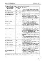
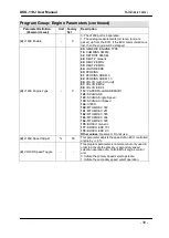
Program Group: Engine Parameters (continued)
Parameter Definition,
(Password Level)
Unit Factory
Set
Description
(2)
Crank Timer
sec
10
This is the maximum start period. Starting will be
automatically cancelled if the genset fires before the
timer.
(2)
Wait Between Starts
sec
10
This is the waiting period between two start
attempts.
(1)
Engine Heating Timer
sec
4
This is the period used for engine heating following
the program parameter.
(1)
Cooldown Timer
min
1.0
This is the period that the generator runs for cooling
purpose after the load is transferred to mains.
(1)
Stop Solenoid Timer
sec
10
This is the maximum time duration for the engine to
stop. During this period the STOP relay output is
energized (if assigned by
Relay Definitions
). If the
genset has not stopped after this period, a
FAIL TO
STOP
warning occurs.
(2)
Number of Starts
-
3
This is the maximum number of start attempts.
(2)
Choke Timer
sec
5
This is the control delay of CHOKE output.
The choke output is activated together with the
crank output. It is released after this delay or when
engine runs (whichever occurs first).
(2)
Engine Heating Method
-
0
This parameter defines the engine heating method.
The genset will not take the load before engine
heating is completed.
0:
engine is heated during
Engine Heating Timer
.
1:
engine is heated until the coolant temperature
reaches the
Engine Heating Temperature
and at
least during the
Engine Heating Timer
.
(1)
Service Engine Hours
hour
50
The
SERVICE REQUEST
led indicator will turn on
after this quantity of engine hours from the last
service. If the period is set to „0‟ no
SERVICE
REQUEST
will be generated depending on engine
hours.
(1)
Service Period
month
6
The
SERVICE REQUEST
led indicator will turn on
after this amount of time from the last service. If the
period is set to „0‟ no
SERVICE REQUEST
will be
indicated depending on time.
(2)
Idle Speed Timer
sec
0
When the engine runs, the Idle output relay function
will be active during this timer.
(2)
Gas Solenoid Delay
sec
5
The gas solenoid of the gas engine will be opened
after this delay during cranking.
(1)
Low Fuel Warning
%
20
If the fuel level measured from the analog input falls
below this limit, a
LOW FUEL LEVEL SENDER
warning is generated.
(2)
Low Fuel Shutdown
%
10
the fuel level measured from the analog input falls
below this limit, a
LOW FUEL LEVEL SENDER
shutdown alarm is generated and the engine stops.
(2)
Fuel Consumption per
Hour
%
0
This parameter is the threshold for sending FUEL
THEFT and FUELLING sms messages.
If this parameter is set to 0, then no Fuel Theft and
Fuelling sms messages will be sent.
If SMS is required, set this parameter to a value
above the hourly fuel consumption of the genset.
(2)
Fuel Level sender Ohms
ohms
180
Fuel level sender max resistance. 180 ohms and 300
ohms senders are common.

