Data General AViiON 530 Series Скачать руководство пользователя страница 208

Technical Specifications

A-12

014–002091

Integrated I/O Connectors and Signals

This section lists the I/O connectors and signals available on the AViiON 530 and 4600

computer system and system bus daughter boards. For a description of VMEbus

connectors and pin assignments, refer to

Setting Up and Installing VMEbus Options in

AViiON

Systems.

Asynchronous Serial Port Connectors

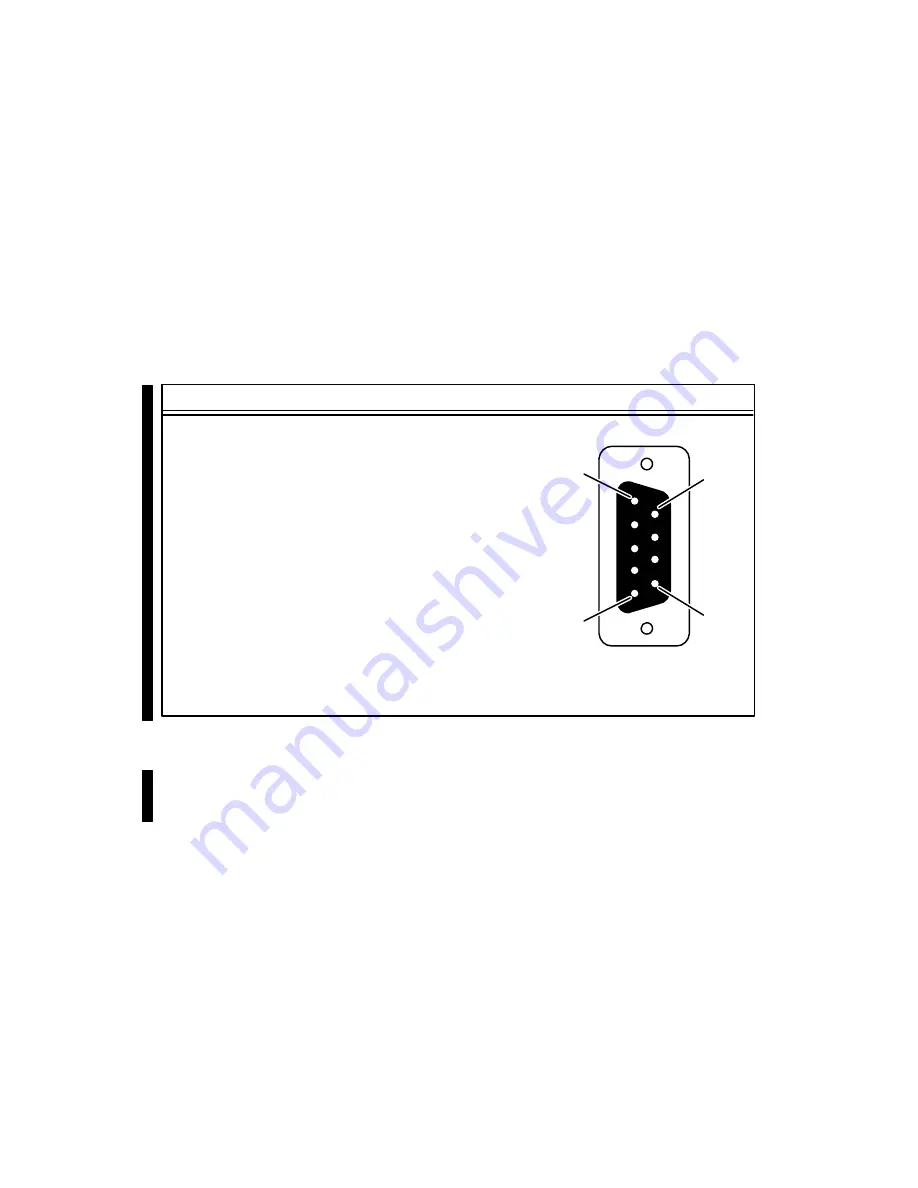
Serial devices connect to the RS-232-C ports through one of three 9-pin, male
D-connectors located on the back of the computer unit. Figure AĆ1 lists the signals
and shows the pin numbers for these serial connectors, labeled A, B, and C.

Pin Signal

*1

Data Carrier Detect <

2

Receive Data <

3

Transmit Data>

4

Data Terminal Ready >

5

Signal Ground

6

Data Set Ready < (ports B and C only)

7

Request to Send >

8

Clear to Send <

9

Ring Indicator < (ports B and C only)

*Proper terminal operation while running the DG/UX

operating system requires the DCD signal pulled up by the
presence of a system board jumper. We describe this jumper
in Chapter 10.

5

9

1

6

(Male)

 Figure A-1 Asynchronous Serial Port (RS232A–C) Connector Signals

An adapter cable (part number 005-38420) converts signals from the 9-pin connector

on the computer bulkhead to a 25-pin cable connector. Figure AĆ2 shows the 9- to

25-pin conversion accomplished by the asynchronous adapter cable.

Figure AĆ2 also shows the signal routing in the DB25-to-DB25 cables used with the

adapter cable to connect modems and terminals to the AViiON 530 and 4600 series

computer bulkhead.

Содержание AViiON 530 Series

Страница 1: ...Customer Documentation P R O D U C T L I N E...

Страница 2: ......

Страница 3: ...xpanding and Maintaining AViiON 530 and 4600 Series Computers 014 002091 01 Copyright Data General Corporation 1991 1992 All Rights Reserved Printed in the United States of America Rev 01 June 1992 Or...

Страница 4: ...Drawing Board CEO DXA CEO Light CEO MAILI CEO Object Office CEO PXA CEO Wordview CEOwrite COBOL SMART COMPUCALC CSMAGIC DASHER One DASHER 286 DASHER 286 12c DASHER 286 12j DASHER 386 DASHER 386 16c DA...

Страница 5: ...WARNING Changes or modifications to this unit not expressly approved by the party responsible for compliance could void the user s authority to operate the equipment This device complies with Part 15...

Страница 6: ......

Страница 7: ...nstructions for using the System Control Monitor SCM and suggestions for solving powerup problems NOTE This manual does not describe how to set up or install VMEbus option boards or the devices that c...

Страница 8: ...should follow each time you add or replace an internal system component and describes how to respond to hardware problems Explains how to review system configuration parameters and provides instructi...

Страница 9: ...nnected to the system board whose operating parameters conflict with the defaults listed in Chapter 2 and which are required for the first powerup read the appropriate instructions in Chapter 5 before...

Страница 10: ...cted to your system refer to Setting Up and Installing VMEbus Options in AViiON Systems Internal CRUs An internal CRU Customer Replaceable Unit is any component you can replace that is housed inside t...

Страница 11: ...the power supply line cord fan and provides general instructions for replacing a drive Lists physical electrical and environmental specifications of the subsystem Installing and Operating the Model 1...

Страница 12: ...which provides operating system support to client computers across a local area network Some computers function as both stand alone and network servers The term client refers to any computer that rece...

Страница 13: ...DG HELPS Lines are open from 8 00 a m to 5 00 p m your time Monday through Friday The center will put you in touch with a member of Data General s telephone assistance staff who can answer your questi...

Страница 14: ...Preface xii 014 002091...

Страница 15: ...es 2 3 Connecting the Keyboard AViiON 530 Series 2 5 Connecting the Mouse AViiON 530 Series 2 6 Connecting a Local Area Network Cable 2 8 Connecting Asynchronous Devices 2 10 Connecting Synchronous De...

Страница 16: ...nging the Keyboard Language 5 12 Changing the Screen Saver Timeout 5 14 Changing Modem Port Parameters 5 15 Changing the Modem Port Baud Rate 5 16 Changing the Modem Port Character Size 5 17 Changing...

Страница 17: ...ory Modules 8 6 Chapter 9 Adding or Replacing a CPU Complex and System Board Options Adding or Replacing a CPU Complex Board 9 2 Removing a CPU Complex Board 9 2 Specifying CPU Configurations 9 4 Inst...

Страница 18: ...s Storage Options A 5 Power Subsystem Specifications A 6 Workstation Peripherals Specifications AViiON 530 Series A 8 Integrated I O Connectors and Signals A 11 Appendix B Using the System Control Mon...

Страница 19: ...2 SCSI Device Identification Numbers 7 8 8 1 Valid Memory Configurations 8 4 A 1 Internal Component Current Requirements for AViiON 530 and 4600 A 7 B 1 SCM Line Editing Features and Keyboard Control...

Страница 20: ...ecting Devices to the Computer Unit Serial Ports 2 11 2 10 Connecting a Synchronous Device to the Computer Unit 2 12 2 11 Connecting a Parallel Printer to the Computer Unit 2 13 2 12 AViiON 530 and 46...

Страница 21: ...5 7 6 Removing Brackets from Drives 7 6 7 7 Example of Recommended SCSI ID Settings 7 8 7 8 Bracket Mounting Holes for Drives 7 9 7 9 Attaching Brackets to Drives 7 10 7 10 Removing or Replacing a Fil...

Страница 22: ...9 15 9 19 Releasing the Graphics Monitor Connectors from the Computer Bulkhead 9 16 9 20 Removing the Board Retaining Screws 9 17 9 21 Separating the Interboard Connectors 9 17 9 22 Removing the Grap...

Страница 23: ...r Unit 12 3 12 4 Removing the Power Supply 12 3 12 5 Setting the Voltage Selection Switch 12 4 12 6 Inserting the Power Supply into the Computer Unit 12 5 12 7 Securing the Power Supply to the Compute...

Страница 24: ...Contents xxii 014 002091...

Страница 25: ...ms support a variety of configurations AViiON 4600 series computers function primarily as the basis of multiuser or server systems AViiON 530 computers add graphics options to the same basic system to...

Страница 26: ...ver not included One integrated NCR small computer system interface SCSI controller for internal maximum of four and external bus maximum of seven SCSI mass storage devices One central processing unit...

Страница 27: ...roller One 24 bit Z buffer board for enhanced graphics performance AViiON 530 series Mass Storage Devices Maximum of four total of the following Removable media devices maximum of two 1 4 inch cartrid...

Страница 28: ...88 6589 reel to reel SCSI tape drives 3 synchronous devices per VSC 3 controller 16 asynchronous devices per VAC 16 controller 255 asynchronous devices per VDA 255 adapter AViiON 4600 series Controlle...

Страница 29: ...l and Connectors About the System Console AViiON 4600 Series The term system console refers to a terminal with a keyboard that receives powerup diagnostic test messages and from which you bring up you...

Страница 30: ...torted pressing the Degauss switch demagnetizes the monitor screen and clears any associated distortion If you did not order Data General s Model G6487 graphics monitor you can use another graphics mo...

Страница 31: ...LAN VME LAN Controller with a connector for a second Ethernet LAN transceiver Supplements the Ethernet connection managed by the integrated LAN controller s on the system board and optional I O expans...

Страница 32: ...ou complete the Installation Checklist Figure 1 9 at the end of this chapter before proceeding with any of these installation procedures Before You Start Before setting up your system you need to prep...

Страница 33: ...one by one and remove the equipment As you do so inspect the equipment carefully for visible damage CAUTION Handle your computer equipment carefully do not drop or jar it Lift by grasping firm surface...

Страница 34: ...hown Pivot edge Figure 1 5 Positioning the Computer Unit Upright Tilt the computer unit on the packing tray edge opposite the shipping tray Slide the shipping tray out from under the foam and cardboar...

Страница 35: ...one side and balance the stand legs beside the cut outs on the packing tray foam A Push down Pull up Pull out Repeat the process illustrated in A on the opposite side to release the entire computer u...

Страница 36: ...uffixes Table 1 1 lists voltage suffixes by country for your computer unit power cord and for graphics monitor power cords Verify that the voltage for both is appropriate for your site Table 1 1 Volta...

Страница 37: ...packaged separately with the device Use Table 1 2 to record the cables you received for integrated system components With the exception of the asynchronous adapter cables you receive only those cables...

Страница 38: ...78E005 10 ft 3 05 m cable 005 037724 15378E010 15 ft 4 6 m cable 005 036625 15378E015 Asynchronous 9 to 25 pin Adapter Cables 005 038420 N A Synchronous Devices 6 ft 1 83 m EIA RS 232 cable 005 032917...

Страница 39: ...ap outlines the path we recommend that you follow through the installation documentation The Installation Checklist on the following page summarizes the hardware and software installation manuals you...

Страница 40: ...grated LAN s DG Token Ring Local Area Network Installation Guide for information about installing token ring network hardware Using AViiON System Diagnostics for information about using the hardware a...

Страница 41: ...an overview of the computer system hardware components refer to Chapter 1 CAUTION Do not apply power to the computer unit while setting up your computer system Refer to Chapter 3 in this manual for p...

Страница 42: ...ll need a small flat head screwdriver to complete these steps Refer to Figure 2 1 as you perform the first three steps 1 Align the holes in the 9 pin end of the asynchronous adapter cable to the pins...

Страница 43: ...supports different terminal characteristics refer to Chapter 5 for information about changing the console port parameters after your first powerup NOTE SCM menus refer to the port labeled RS232 A as t...

Страница 44: ...trips near the connector ends Connect the red cable to the R monitor connector the green cable to the G MONO connector and the blue cable to the B connector as shown in Figure 2 3 Turn the ends of the...

Страница 45: ...4 illustrates how to connect the monitor cord R G B H V FUSE Monitor rear view Figure 2 4 Connecting the Color Monitor Power Cord Connecting the Keyboard AViiON 530 Series Follow these steps to conne...

Страница 46: ...steps to connect the mouse device to the computer unit Reverse the order of these instructions to remove a faulty mouse in order to replace it CAUTION Do not try to remove or replace your mouse while...

Страница 47: ...he left for left handed use 3 Attach the female end of the mouse extension cable to the end of the mouse cable then plug the other end of the extended mouse cable into the rear panel of the computer u...

Страница 48: ...t installing VMEbus options AViiON 530 or 4600 series systems use the following cables to connect an integrated Ethernet LAN to the rear panel connector s Cable Cable Cable type part number model numb...

Страница 49: ...clip mounts on the cable can pass through then push the cable firmly into the connector 3 Once the cable and clip mounts are secured to the connector slide the clip using your screwdriver or a compar...

Страница 50: ...driver or similar tool to complete these steps Refer to Figure 2 9 as you perform the first three steps 1 Plug the 9 pin female end of the asynchronous adapter cable into one of the three male connect...

Страница 51: ...to ports RS232 A RS232 B and RS232 C have the following characteristics 9600 baud 8 data bits No parity ANSI character set Enabled flow control NOTE These default settings are applied to all three as...

Страница 52: ...ft Synchronous modem 005 032917 15290E006 6 005 032918 15290E015 15 005 032919 15290E025 25 1 Plug one end of the synchronous communication cable into the COM A or COM B connector on the back of the...

Страница 53: ...LPT1 005 033762 15293E030 30 interface 1 Plug the 25 pin end of the printer cable into the parallel printer connector on the back of the computer unit as shown in Figure 2 11 Attach the printer cable...

Страница 54: ...led If a large black plug occupies the rear panel connector s labeled SCSI and you have no external SCSI devices you can skip this section and continue with the next section Connecting the Computer Un...

Страница 55: ...aight down or straight up into the brackets on the terminator plug as shown in Figure 2 14 Your vertical pressure will push the clips into place do not squeeze or pull the clips out of shape 4 Push th...

Страница 56: ...Country 120 volt 109 996 US 100 volt 109 996 1 US Canada 240 volt 109 813 5 UK1 240 volt 109 809 6 Australia 220 volt 109 812 7 Europe2 220 volt 109 811 8 Italy 220 volt 109 815 9 Denmark 220 volt 10...

Страница 57: ...ystem hardware continue with the steps in Chapter 3 to ensure that the computer system starts properly to become familiar with powerup procedures and to verify that the computer system hardware passes...

Страница 58: ...Setting Up Your Computer System 2 18 014 002091...

Страница 59: ...p your system and describe what you should do the first time you start up your AViiON 530 or 4600 series computer Once you install and customize your operating system the sequence of events and displa...

Страница 60: ...l Figure 3 1 Monitor Power Switch 2 If you have a Peripheral Housing Unit PHU a combined storage subsystem CSS2 DC or another external peripheral unit connected to your computer system turn on power t...

Страница 61: ...Chassis Front Panel Diagnostic LED Power off O Power on l AViiON Figure 3 3 Computer Unit Power Switch and LED Power On Indicator 5 Watch the system console or graphics display monitor on an AViiON 5...

Страница 62: ...AViiON 530 series If your display does not appear as described turn power off to the computer unit to the graphics or nongraphics console and to all connected peripherals wait approximately one minut...

Страница 63: ...up testing completes Your screen display indicates the disk and file that your computer system is attempting to boot as follows Booting sd ncsc 0 root dgux installer i What happens next depends on whe...

Страница 64: ...o the way you set up your system hardware Then try to boot the DG UX installer operating system manually by typing the following command line at the SCM prompt SCM If the DG UX installer operating sys...

Страница 65: ...your system has simply failed to boot the DG UX installer operating system Proceed now to your operating system documentation for installation instructions For information about the SCM configuration...

Страница 66: ...sks You may also want to power down if your computer system is experiencing intermittent errors often the process of restoring hardware components to the powerup state resolves temporary problems or i...

Страница 67: ...operating system is running may result in lost data Always try to shut down your operating system before resetting your computer system Computer Unit Chassis Rear Panel RESET ABORT Figure 3 4 Computer...

Страница 68: ...witch by using the SCM RESET command while at the SCM prompt as follows SCM or SCM Restarting Your System Each time you turn power on your system goes through powerup testing and its automatic boot se...

Страница 69: ...systems housed outside the computer unit you will need the information in the Connecting an External SCSI Bus to the Computer Unit Rear Panel section of this chapter to connect those devices to your c...

Страница 70: ...ed as Controller 1 The second controller supports a bus extending from the connector marked SCSI B on the rear panel Each SCSI bus in your system can support a total of seven devices housed internally...

Страница 71: ...installed devices mounted either inside the computer unit or mounted inside a mass storage housing unit the SCSI ID numbers are already set If you add or replace devices anywhere on the SCSI bus you m...

Страница 72: ...operating system allows the configuration of any SCSI device at any unique and valid SCSI device ID number However other software such as device drivers could limit the use of certain device ID numbe...

Страница 73: ...ge drives Before you connect the SCSI bus cable to your computer unit make certain each device on the bus has a unique SCSI ID if you notice a conflict you will need to reassign device identifications...

Страница 74: ...roller and a bus connector SCSI B that supports an external SCSI bus with a cable maximum of 18 6 feet Only 1 foot of the 19 6 foot cable maximum resides within the AViiON 530 or 4600 series computer...

Страница 75: ...y an external terminator plug to terminate the SCSI bus if your drive does not have an external terminator and will be physically positioned as the last drive on the SCSI bus you must install bus term...

Страница 76: ...A Slot Device SCSI Adapter Board half height left half height right full height half height left half height right Cable Length 4 75 feet Total Cable Length 19 6 feet maximum full height External Mas...

Страница 77: ...h 4 75 feet Total Cable Length 19 6 feet maximum full height External Mass Storage Devices external connector port B Drive Type SCSI ID Device Total Cable Length 19 6 feet maximum Cable Length x x x 3...

Страница 78: ...ore you begin physically installing your SCSI bus and SCSI devices plan your cabling scheme s and assign SCSI ID numbers to each device according to the rules described in the preceding sections of th...

Страница 79: ...licts with your SCSI bus plan NOTE Each SCSI drive or SCSI adapter board located in a mass storage subsystem must have its own unique ID number 3 Refer to the device specific documentation for each dr...

Страница 80: ...I cable Refer to your device specific documentation for instructions and then install each device along the bus Terminating the SCSI Bus Make certain to properly terminate each SCSI bus on your system...

Страница 81: ...slot marked SCSI B will not contain a connector Figure 4 7 AViiON 530 and 4600 Series External SCSI Connectors After you verify that the cable lengths and SCSI IDs in your configuration adhere to the...

Страница 82: ...shaped connector and gently insert the cable in the rear panel connector as shown in Figure 4 9 Connector lines pins 1 50 Rear panel connector female SCSI bus cable Bus connector male Figure 4 9 Plugg...

Страница 83: ...o complete your installation and connect the ac power cord Then continue with Chapter 3 Starting and Stopping Your Computer System for instructions on powering up a system with external peripherals If...

Страница 84: ...Setting Up and Installing a SCSI Bus 4 16 014 002091...

Страница 85: ...enus and information about using them The rest of this chapter describes how to use menu items to accomplish common tasks Summary of Menus and Menu Conventions You access all SCM menus from the View o...

Страница 86: ...n 1 Change default system boot path 2 Change console parameters 3 Change modem port parameters 4 Change mouse parameters 5 View system configuration 6 Change VME A24 configuration 7 Return to previous...

Страница 87: ...he SCM begins an automatic boot sequence after powerup testing completes The SCM uses the default system boot path to find the automatic boot device It uses this same default system boot path whenever...

Страница 88: ...k name dir file Boot device specification first stage boot File path second stage boot Figure 5 2 Full Boot Path Format NOTE The syntax for booting over a LAN is slightly different refer to the sectio...

Страница 89: ...ating system You can use this second stage or file path argument to specify any executable file or program parameter such as run level Refer to Appendix B for details For example the file path refers...

Страница 90: ...ally specify the Internet address of the server system For example the following boot path specifies the server at Internet address on the integrated Ethernet LAN Examples of Valid Boot Paths NOTE The...

Страница 91: ...ifferent LANs managed by an integrated and a VME Ethernet controller SCM b hken 128 111 5 6 Using the Change Default System Boot Path Menu To view initialize change and optionally boot the default boo...

Страница 92: ...boot path 6 To boot type and press New Line Do you want to boot N Y The next message you see is from the program you booted Changing Console Parameters Items on the Change Console Parameters menu allo...

Страница 93: ...ion of keyboard control sequences Changing the System Console Baud Rate While in the View or Change System Configuration menu type and press New Line to select item 2 Change console parameters The sys...

Страница 94: ...s the Change Console Parameters menu with the current value in brackets next to item 2 Change character length Use item 2 to change the default character size for your system console port The default...

Страница 95: ...nt value in brackets next to item 3 on the Change Console Parameters menu Use item 3 Change async console mode to change the default character code setting for the system console port The default char...

Страница 96: ...you can use item 4 Change flow control to enable or disable the default flow control setting while in the SCM The system displays the current value in brackets on the Change Console Parameters menu Ch...

Страница 97: ...lish 2 Type and press New Line to select item 5 Change console language The system displays the Change Console Language menu as follows Change console language 1 U S English 2 German 3 U K English 4 F...

Страница 98: ...e Danish Norwegian Portuguese NOTE When you initialize a keyboard language using item 10 Other the console language remains U S English within the SCM however the SCM passes the alternate language typ...

Страница 99: ...a new prompt where you enter the number of minutes you want the monitor screen to remain on before it goes blank Enter new timeout value 5 You return to the Change Console Parameters menu with the new...

Страница 100: ...the appropriate section below Changing the Modem Port Baud Rate The default baud rate for the modem port is 1200 baud The system displays the current baud rate in brackets Refer to the documentation t...

Страница 101: ...2 7 bit even parity 3 7 bit odd parity 4 7 bit mark parity 5 7 bit no parity 6 Return to previous screen Current character size is 8 bit no parity Enter choice s The next time you reset or restart you...

Страница 102: ...It shows memory module numbers for each available slot and lists whether the slot contains a memory module or not The following example shows the memory configuration display for a computer with one p...

Страница 103: ...oads and verifies the MAD and VAD to default values The Change VME A24 configuration menu allows you to change this default A24 space mapping An A24 board that directs data transfers between itself an...

Страница 104: ...Change VME A24 configuration 1 VME A24 Page 0 DTB Slave Mode VME to MBUS 2 VME A24 Page 1 DTB Master Mode MBUS to VME 3 VME A24 Page 2 DTB Slave Mode VME to MBUS 4 VME A24 Page 3 DTB Master Mode MBUS...

Страница 105: ...this chapter explain how to open and close the computer unit NOTE For information on the periodic maintenance of individual system components such as tape disk and diskette drives refer to the device...

Страница 106: ...ding Electrostatic Discharge ESD Damage so that you do not damage the replacement or add on CRU NOTE If you have determined that the problem is in the peripheral housing unit PHU refer also to the man...

Страница 107: ...output If the new configuration exceeds system power limits you will need to eliminate some part of the proposed system This section explains how to calculate and compare the necessary power informati...

Страница 108: ...d by each power source continue verifying your power requirements by calculating the wattage total for the planned system 4 Multiply the number of volts from each dc power source 5 12 and 12 by the co...

Страница 109: ...1 5 NA 7 3 5 diskette 0 51 1 0 NA 8 VME options 9 slot 1 VSC 3 sync controller 3 4 07 07 10 slot 2 VAC 16 async controller 4 5 25 25 11 SCSI adapter board for Diskette 07 12 13 14 Power Supply Limits...

Страница 110: ...te 0 51 1 0 NA 8 VME options 9 slot 1 VSC 3 sync controller 3 4 07 07 10 slot 2 VAC 16 async controller 4 5 25 25 11 SCSI adapter board for Diskette 07 12 13 14 Power Supply Limits must exceed Calcula...

Страница 111: ...V Total amperes max 12 V Total amperes max 12 V Total amperes max Wattage volts x amperes drawn 5 V wattage total 5 x A W 12 V wattage total 12 x A W 12 V wattage total 12 x A W Power supply output wa...

Страница 112: ...ou remove covers and panels from the equipment The chapters on adding or replacing a subassembly list required tools and materials at the beginning of the procedures After you remove a cover or panel...

Страница 113: ...n you install new or replacement devices in your system you often need to specify configuration parameters by setting jumpers and or switches on the individual devices This section explains how to phy...

Страница 114: ...ushing jumpers straight onto the proper pins then push the jumper completely onto the pins with your finger if necessary You should not need to force a jumper into place if you install the proper jump...

Страница 115: ...driver to open the computer unit The following steps tell you how to remove the side and top covers from the computer unit s housing Removing the Side Covers 1 Power down the computer system Refer to...

Страница 116: ...91 Computer unit right side Loosen fastener 1 4 turn Figure 6 5 Loosening the Side Cover Fasteners 4 While supporting the side cover lift it up and away from the computer unit as shown in Figure 6 6 C...

Страница 117: ...down the computer system Refer to the Shutting Down Your Computer System section of Chapter 3 for the proper procedure to power down the computer system WARNING To avoid electrical shock or equipment...

Страница 118: ...uter Unit This section tells how to reinstall the computer unit s top and side covers You must install the top cover before you install the side covers Installing the Top Cover To reinstall the top co...

Страница 119: ...gure 6 9 Installing the Top Cover Installing the Side Covers After installing the top cover follow the steps below to reinstall one or both side covers You will need a coin or a large flat blade screw...

Страница 120: ...re 6 11 Installing the Side Covers 4 Using a coin or screwdriver turn the two fasteners one quarter turn clockwise as shown in Figure 6 12 to lock the cover in place Computer unit right side Tighten f...

Страница 121: ...ower cord into the receptacle on the back of the computer unit as shown in Figure 6 13 Power cord Computer Unit Rear Panel Figure 6 13 Connecting the Computer Unit s Power Cord 7 Plug the other end of...

Страница 122: ...Expanding and Maintaining Your Computer System 6 18 014 002091...

Страница 123: ...UX System Documentation lists the manuals that support the mass storage devices available in AViiON 530 and 4600 series systems NOTE Before you add or replace any mass storage device refer to Chapter...

Страница 124: ...height Digital audio tape 6762 Half height 1 Some versions include 3 1 2 to 5 1 4 inch conversion brackets Mass Storage Device Locations Your computer unit has the two slots for internal SCSI drives a...

Страница 125: ...eplacement drive 4 Attach the brackets to the replacement drive 5 Reinstall the drive assembly in the computer unit Removing a Drive Assembly Before you can remove a drive assembly you should remove t...

Страница 126: ...el Device connectors SCSI bus internal cable SCSI device power cables Figure 7 2 SCSI Bus Ribbon Cable and Device Power Connectors I O bus cable Typical diskette drives SCSI adapter board Computer uni...

Страница 127: ...drive power cable connectors Typical diskette drives Figure 7 4 Unplugging the Power Adapter Cable from a Diskette Drive 4 Remove the eight screws and washers securing the drive assembly to the comput...

Страница 128: ...om the drive you are replacing follow the steps below You will need a medium 2 Phillips screwdriver 1 Remove the eight screws and washers four for each bracket that secure the drive to the brackets If...

Страница 129: ...trol option jumpers or switches for sequential drive motor start The drive will then delay starting up its spindle motor a number of seconds a multiple of the SCSI ID number when you power up your sys...

Страница 130: ...ond drive 5 Third drive 6 1 A CD ROM drive can have any SCSI ID except 0 or 4 2 Or as the next disk in sequence Second disk drive SCSI ID 1 Second tape drive SCSI ID 5 First tape drive SCSI ID 4 First...

Страница 131: ...the bracket with the holes in the side of the drive A half height drive fills half of the bracket Figure 7 8 shows the mounting holes for for each type of drive 4 3 2 1 1 6 2 3 4 332 Mbyte disk 2 or 4...

Страница 132: ...ion Completing the Drive Assembly Installation to complete the installation of the drive Completing the Drive Assembly Installation To complete the installation of the drive follow the steps below You...

Страница 133: ...the screwdriver to release the plastic tab on the filler panel Once you do this the filler panel will pop out 2 Position the drive in the slot so that its back connector end faces toward the center of...

Страница 134: ...information on the connector locations refer to the manual for installing the drive NOTE You can plug the cable in only one way the connector on the power cable has beveled edges to match the power co...

Страница 135: ...u are installing the first diskette drive you will not have installed the SCSI adapter board yet Figure 7 13 Plugging the I O Bus Cable into a Diskette Drive If you installed the first diskette drive...

Страница 136: ...to the section Installing the SCSI Adapter Board If you are replacing the SCSI adapter board continue to the next section Removing the SCSI Adapter Board Removing the SCSI Adapter Board Before you can...

Страница 137: ...e from the SCSI Adapter Board 3 Remove the two screws securing the SCSI adapter board to the front of the left side of the computer unit as shown in Figure 7 16 SCSI adapter board Computer unit top an...

Страница 138: ...ives CAUTION Unless you are properly grounded you can discharge static electricity and damage components in the system To install the SCSI adapter board in the computer unit follow the steps below 1 P...

Страница 139: ...side covers as described in the section Closing the Computer Unit in Chapter 6 Replacing the Terminator Plug The computer uses a SCSI bus terminator plug that ships installed in the external SCSI conn...

Страница 140: ...plug the terminator plug from the SCSI bus connector Terminator plug Spring clip SCSI connector on computer unit or subsystem Spring clip Figure 7 19 Unplugging and Plugging in the SCSI Bus Terminator...

Страница 141: ...7019 modules provide 16 megabytes Both models support Error Checking and Correction ECC rather than byte parity error detection Figure 8 1 shows how to identify the memory modules supported by your s...

Страница 142: ...he right Never leave a connector empty between memory modules You must configure memory modules in vertical pairs on the system board Odd numbers of modules will not work in AViiON 530 or 4600 series...

Страница 143: ...ple assume memory modules occupy connectors 0 through 7 You can remove the memory module in connector 3 only after connectors 5 and 7 are unoccupied To replace the module in connector 3 you must first...

Страница 144: ...ve any memory modules you must remove the computer unit s right side cover and attach the ESD wrist strap as described in the Opening the Computer Unit section of Chapter 6 CAUTION Unless you are prop...

Страница 145: ...Memory module System board side view Figure 8 4 Releasing the Memory Module Locking Tabs 2 With the locking tabs released raise the memory module to about a 20 30 angle as shown in Figure 8 5 then gen...

Страница 146: ...stall a new memory module Installing Memory Modules Before you can install any memory modules you must remove the computer unit s right side cover and attach the ESD wrist strap as described in Chapte...

Страница 147: ...emory module Insert module into connector at an angle then push left to lock in place System board Figure 8 6 Installing the Memory Module in the Connector Repeat steps 1 and 2 to install or reinstall...

Страница 148: ...Adding or Replacing Memory Modules 8 8 014 002091...

Страница 149: ...on restraints described in Chapter 6 your system can also include a second CPU complex an Input Output I O expansion board and an 8 bit or 24 bit graphics controller board Systems with a graphics cont...

Страница 150: ...mplex board used in AViiON 530 and 4600 series systems 88100 88200 88200 AV530 4600 4620 Figure 9 2 AViiON 530 and 4600 Series CPU Complex A CPU complex board contains one Motorola 88100 central proce...

Страница 151: ...unded you can discharge static electricity and damage components in the system To remove the CPU complex board use the following steps You will need a medium Phillips screwdriver 1 Remove the two scre...

Страница 152: ...hapter 10 Replacing the System Board Otherwise continue to the next section Specifying CPU Configurations before installing the new CPU complex board Specifying CPU Configurations Your system uses jum...

Страница 153: ...CMMUs Figure 9 6 CPU Configuration Jumpers on the System Board NOTE Incorrectly configured system and CPU complex boards will cause your system to fail powerup Two CPU complex boards within a single...

Страница 154: ...only CPU complex Jumper installed 88200 88200 88200 88200 88100 88200 88200 First or only CPU complex Second CPU complex Jumper installed First or only CPU complex AV 4605 and 4625 CPU designator jum...

Страница 155: ...ticular care when handling the AV4605 4625 CPU complex do not apply pressure to the clear plastic that covers the 88100 88200 components NOTE When you install two CPU complex boards attach the first c...

Страница 156: ...se system includes a Small Computer System Interface SCSI controller and an Ethernet LAN controller integrated onto the system board This section describes how to add or replace an Input Output I O ex...

Страница 157: ...u must prepare a worksite remove the computer unit s right side and attach the ESD wrist strap as described in Chapter 6 Expanding and Maintaining Your Computer System CAUTION Unless you are properly...

Страница 158: ...02091 Computer unit top and right side cover removed System board SCSI B bus cable Figure 9 11 I O Expansion Board SCSI Ribbon Cable 3 Remove the two screws that secure your I O expansion board to the...

Страница 159: ...connectors on the back of the board from the connectors on the system board as shown in Figure 9 13 CAUTION Grasp the board at its edges to avoid damaging any components on the board System board brac...

Страница 160: ...g an I O Expansion Board Before you can install an I O expansion board you must prepare your worksite remove the computer unit s right side and attach the ESD wrist strap as described in Chapter 6 Exp...

Страница 161: ...board CAUTION If you need to set the option board down put it back inside the antistatic shipping bag 3 Position the Ethernet LAN connector in the openings provided by the system board bracket and th...

Страница 162: ...the Computer Unit Bulkhead To install a replacement I O expansion board or to reinstall one removed for access to the system board skip Step 5 through Step 7 and continue with Step 8 To install a new...

Страница 163: ...es without altering the cable fold and replace the cable clamp over all three cables Figure 9 18 shows how to properly install the SCSI B ribbon cable 8 Attach the ribbon cable from the SCSI B connect...

Страница 164: ...ther diagnostic utilities Adding or Replacing a Graphics or Z Buffer Board 530 series This section explains how to add a graphics or z buffer board to your computer unit and to replace a failed graphi...

Страница 165: ...er boards follow the steps below You will need a medium Phillips screwdriver If you are installing a graphics controller board you might also need a flat blade screwdriver and a medium sized adjustabl...

Страница 166: ...3 Separate the interboard connector on the back of the top board from the interboard connector on the board behind it as shown in Figure 9 22 CAUTION Grasp the board at its edges to avoid damaging any...

Страница 167: ...replace the system board proceed to the next chapter Replacing the System Board Installing the Graphics or Z Buffer Board Before you can install a graphics board or z buffer board you must remove the...

Страница 168: ...les in the computer unit bulkhead before continuing with this step Align the interboard connectors and press them together as shown in Figure 9 24 If you cannot press the connectors together make sure...

Страница 169: ...shorter board retaining screws and replace them with the two longer board retaining screws shipped with the z buffer board 5 If you are installing a graphics controller board install the hexagonal ret...

Страница 170: ...onnect a graphics display monitor mouse and keyboard to your system refer to Chapter 2 Setting Up your Computer System To test a new or replacement board you should run a diagnostics acceptance test a...

Страница 171: ...System Board Before you can remove the system board you need to prepare your worksite remove the computer unit s right side cover and attach the ESD wrist strap as described in Chapter 6 Expanding and...

Страница 172: ...in Figure 10 2 that secure the system board bracket to the back of the computer unit Remove seven screws Computer unit back Remove filler plate Remove seven screws Figure 10 2 Releasing the System Bo...

Страница 173: ...Board 7 Using the medium Phillips screwdriver remove the eight screws shown in Figure 10 4 that secure the system board to the computer unit Remove eight screws System board Figure 10 4 Unscrewing th...

Страница 174: ...9 Remove the system board by pulling its bracket away from the computer unit and then lifting the board out of the computer unit as shown in Figure 10 6 CAUTION Grasp the system board by its edges to...

Страница 175: ...this original PROM on the replacement system board 13 Insert the failed system board in an antistatic bag To install the replacement system board go to the next section Installing the System Board In...

Страница 176: ...Figure 10 8 Once the pins are in line on one side repeat this procedure with the other side of the component Angled pin Spread pins PROM component pin positions Straight pins Straightening PROM compo...

Страница 177: ...Single CPU Two CMMUs Indicates jumper installed Indicates jumper removed CPU complex connector Dual CPUs Four CMMUs CPU Configuration jumpers System board Single CPU Two CMMUs Dual CPUs Twelve CMMUs I...

Страница 178: ...eries System Board NOTE Jumpers installed at asynchronous serial port pins P17 P18 and P19 enable Data Carrier Detect operation by pulling the signal up to 12 V The DG UX operating system requires ins...

Страница 179: ...and then the other Since the pins are surrounded by components you will have to press on the components 8 Using the medium Phillips screwdriver secure the system board to the computer unit with the ei...

Страница 180: ...screws as shown in Figure 10 14 10 Reinstall the rear panel filler plate as shown in Figure 10 14 Computer unit back Install filler plate 2 screws Secure system board bracket 5 screws Figure 10 14 Se...

Страница 181: ...nd Chapter 9 Adding or Replacing a CPU Complex and System Board Options as appropriate 13 If you removed the PROM from the replacement system board you should insert this PROM on the failed system boa...

Страница 182: ...Replacing the System Board 10 12 014 002091...

Страница 183: ...the computer unit before removing any cover from the housing To remove a fan assembly follow the steps below You will need a medium 2 Phillips screwdriver 1 Unplug the fan assembly power cable from t...

Страница 184: ...unit back Support here Figure 11 2 Releasing the Fan Assembly from the Back of the Computer Unit 3 Still supporting the bottom pull the fan assembly out and down to disengage it from the computer uni...

Страница 185: ...bly directly under the computer unit as shown in Figure 11 4 2 Pull the fan assembly power cable up through the hole in the computer unit as shown in Figure 11 4 CAUTION The hole for the fan assembly...

Страница 186: ...sembly in the Computer Unit 4 Use one hand to lift and support the back of the fan assembly in position and align the assembly and computer unit screw holes as shown in Figure 11 6 NOTE The securing b...

Страница 187: ...nstall the side cover as described in the section Closing the Computer Unit in Chapter 6 After closing the computer unit power up any storage subsystems peripheral housing units and other peripherals...

Страница 188: ...Replacing the Fan Assembly 11 6 014 002091...

Страница 189: ...Before you can remove the power supply you need to power down any peripherals and the computer unit and remove the computer unit s top and left side covers as described in the Opening the Computer Uni...

Страница 190: ...mputer unit top and left side covers removed Power supply Tape disk power cable Logic power cable Push clip in to release connector Push clips in to release connector Figure 12 2 Unplugging the Tape D...

Страница 191: ...Lift the power supply up and then out of the computer unit as shown in Figure 12 4 Computer unit top and left side covers removed Power supply Figure 12 4 Removing the Power Supply Return the failed p...

Страница 192: ...set the voltage selection switch to 115 V if it has 220 or 240 V ac power set the switch to 230 V Most sites in the United States and Canada have 120 V ac power If you are not sure about the correct...

Страница 193: ...it 4 Secure the power supply to the computer unit by pushing in the two power supply latches shown in Figure 12 7 Computer unit top and left side covers removed Power supply Power supply latch Push in...

Страница 194: ...it top and left side covers removed Power supply Tape disk power cable Logic power cable Figure 12 8 Connecting the Tape Disk Power and Logic Power Cables 6 Plug the fan assembly power and the ac powe...

Страница 195: ...need to power down any peripherals and the computer unit and remove the computer unit s left side cover as described in the Opening the Computer Unit section of Chapter 6 WARNING Always unplug the po...

Страница 196: ...pheral housing units and other peripherals Then start the computer unit according to the instructions in Chapter 3 and your operating system software documentation Next you should test your computer s...

Страница 197: ...age devices an integrated Ethernet LAN controller and a VMEbus standard backplane AV530 workstations further include a color graphics monitor an optical mouse a keyboard and one or two graphics contro...

Страница 198: ...Technical Specifications A 2 014 002091 Altitude Operating 0 8000 feet 0 2438 meters Storage 0 25000 feet 0 7620 meters Noise 0 40 decibels Quiet Office rating...

Страница 199: ...duplex One mouse port AViiON 530 support One keyboard port AViiON 530 support CPU Complex Board Maximum of two 5 5 x 7 68 inches stacked on system board with two 96 pin DIN connectors One 33 megahert...

Страница 200: ...raphics controller board Maximum of one 3 8 x 5 9 inches stacked on graphics controller with one 96 pin DIN connector Selectable 16 or 24 plane z buffer support 256 Kbyte x 4 DRAMs Fixed internal 24 b...

Страница 201: ...dapter Connected externally via RG62 coaxial cable Eight full duplex asynchronous RS 232 C lines per controller Maximum transfer rate 19 2 Kb s per line One Centronics parallel printer port Signals su...

Страница 202: ...alone tower 10 half height slots supporting maximum of seven 5 25 inch SCSI devices five full height seven half height or combination totaling seven or less Model 10565 Peripheral Housing Unit PHU 12...

Страница 203: ...data transfer rate 15 ms average seek Power Subsystem Specifications This section contains specifications for the power subsystem which includes a modular off line switching converter and cooling fan...

Страница 204: ...t 3 0 0 0 Z Buffer 0 5 0 0 Keyboard 0 5 0 0 Mouse 0 0 015 0 02 Internal Mass Storage Drives 150 Mbyte QIC tape 6577 1 5 1 5 0 525 Mbyte QIC tape 6677 1 5 1 5 0 2 Gbyte tape 6590 2 4 0 65 0 Digital aud...

Страница 205: ...ggle the default horizontal scan rate screen refresh rate and pixel rates to operate with a 60 hertz monitor by using the Ctrl V function described in Appendix C Solving Powerup Problems and Exiting t...

Страница 206: ...ilohertz Period 14 257 milliseconds 1071 hertz Front Porch 0 013 milliseconds 1 hertz Sync Width 0 053 milliseconds 4 hertz Back Porch 0 559 milliseconds 42 hertz Blanking Time 0 626 milliseconds 47 h...

Страница 207: ...dback Protocol Compatible with EIA RS 232 C interface 1200 baud asynchronous serial Power Uses power from RS 232 C interface Maximum current 15 milliamps Maximum voltage 13 2 volts ac Size Mouse 3 75...

Страница 208: ...ct 2 Receive Data 3 Transmit Data 4 Data Terminal Ready 5 Signal Ground 6 Data Set Ready ports B and C only 7 Request to Send 8 Clear to Send 9 Ring Indicator ports B and C only Proper terminal operat...

Страница 209: ...connect to the RS 232 C ports through one of two 25 pin female connectors located on the back of the computer unit Figure A 3 lists the signals and shows the pin numbers for these synchronous communic...

Страница 210: ...25 to 36 pin conversion accomplished by the parallel printer cable Pin Signal 1 Strobe 2 Data 0 3 Data 1 4 Data 2 5 Data 3 6 Data 4 7 Data 5 8 Data 6 9 Data 7 10 Acknowledge 11 Busy 12 Paper End out o...

Страница 211: ...in numbers for the single ended SCSI connector Pin Signal Pin Signal 1 25 Unused 26 Data Bus 0 27 Data Bus 1 28 Data Bus 2 29 Data Bus 3 30 Data Bus 4 31 Data Bus 5 32 Data Bus 6 33 Data Bus 7 34 Data...

Страница 212: ...BROAD36 Ethernet over CATV 10BASET proposed Ethernet over twisted pair or any other 10 MHz AUI compatible MAU or MAU like device that does not require the Control Out signal specified in the AUI defin...

Страница 213: ...hrough an 8 pin DIN connector located on the left side of the computer unit Figure A 8 lists the signals and shows the pin numbers for the keyboard and connector Pin Signal 1 Clock 2 Data 3 Unused 4 G...

Страница 214: ...he computer unit Figure A 9 lists the signals and shows the pin numbers for the connector Pin Signal 1 Request to Send 2 Data Terminal Ready 3 Unused 4 Unused 5 Unused 6 Ground 7 Transmit Data 8 Recei...

Страница 215: ...mming System Control and I O Registers for a description of additional SCM functions not described in this manual Getting to the SCM You can tell you are in the SCM when you see its command interprete...

Страница 216: ...fer to your operating system documentation for information about properly shutting down before halting the system CAUTION Always try to shut down your operating system properly before attempting to ha...

Страница 217: ...o AViiON 4600 Systems and AViiON 530 Workstations Programming System Control and I O Registers Using SCM Commands This section describes SCM command interpreter conventions explains how to execute com...

Страница 218: ...Enter Ctrl I wait until you hear one beep then enter 1 if you have a 70 Hz monitor or enter 2 for a 60 Hz monitor Ctrl Q Resumes SCM output display that was suspended with the Ctrl S sequence Ctrl S...

Страница 219: ...ands and Command Functions period Displays processor status Debugging ATTACH Specifies attached processor Program control system operation 1 BOOT Starts system from bootstrap device System operation C...

Страница 220: ...the number of the attached job processor By default Jp 0 is the attached processor after powerup The system returns the currently attached processor if you use this command without an argument Argumen...

Страница 221: ...system s Internet address When you omit the second argument in a LAN boot the SCM probes the LAN for any server that recognizes your computer s Ethernet address and then boots the default boot file W...

Страница 222: ...able B 3 lists the mnemonic names for bootable devices and defines the optional parameters for each device Table B 3 Mnemonics and Parameters for Bootable Devices ncsc NCR SCSI adapter I O address N A...

Страница 223: ...pecify this controller Mnemonic I O Address Enter one of these values The simplest device specification combines the device mnmonic with the controller parameter specification For example specifies th...

Страница 224: ...cifying a Logical Unit Third Parameter The third parameter specifies a drive s logical unit number LUN You rarely use the third parameter lun it supplies additional information when the second paramet...

Страница 225: ...th argument For example to boot file 1 the second file on a cartridge tape in the drive at SCSI ID 4 the full boot path is Booting over a LAN When booting as an operating system client to a DG UX serv...

Страница 226: ...n can be named by the current defaults You may want to change device configurations to accommodate your operating system or to configure additional devices not supplied by Data General Without the def...

Страница 227: ...ice Alternate Ethernet address For example the default specification for the first VME Ethernet controller jumpered according to its factory configuration is To specify a different Hawk Interphase Eth...

Страница 228: ...on the logical disk from the default system disk SCM b sd ncsc 0 usr stand diags 8 Boot any executable file called in the root directory on the second SCSI disk SCSI ID 1 SCM b sd ncsc 1 root bootfile...

Страница 229: ...asses completely to the continued program Arguments trace count The hexadecimal number of instructions you want the program to execute The system displays the address data and mnemonic in that order a...

Страница 230: ...SCM Configuration Menus for further information about SCM menu items Arguments None Related Commands Boots a device or displays the Change Boot Parameters menu Related Messages None Examples Display t...

Страница 231: ...cntrl unit part Boot a device C Continue D Display all registers E address Examine modify memory E register Examine modify R CR FCR F View Change System Configuration H Display help message I data beg...

Страница 232: ...ou have multiple computers The greater than symbol appears after the text prefix if you change the prompt text to a null text string your prompt is simply the symbol Arguments new prompt Text string o...

Страница 233: ...state Unlike a cold reset power applied to the system a warm reset initiated by software the command or a Reset switch does not initialize memory or run powerup diagnostics Arguments None Related Com...

Страница 234: ...argument Arguments address Memory location at which the processor starts executing trace count The system displays the address data and mnemonic in that order after executing the hexadecimal number of...

Страница 235: ...d at locations specified in the s record header and then verifies checksums Information appended to the last s record notifies the SCM when the entire file has been sent For this command to function y...

Страница 236: ...Using the System Control Monitor B 22 014 002091...

Страница 237: ...lem after consulting your operating system s manuals contact Data General as described in the Preface During a normal powerup your system displays the message Passed before it boots the DG UX operatin...

Страница 238: ...a description of how to use the AViiON System Diagnostics hardware acceptance test The last section of this appendix Exiting the Installer System describes how to leave the DG UX installer system bef...

Страница 239: ...ntact Data General For This Condition Try This Blank or Distorted Display Has the graphics monitor screen Rotate the Brightness dial clockwise been blank for 2 minutes Power down then 1 Test the ac po...

Страница 240: ...the screen been blank for Adjust brightness control to maximum 2 minutes Turn all power off then 1 Test the ac power source with a desk lamp or other electrical device 2 Tighten power cord connection...

Страница 241: ...nect your AViiON 530 series computer components together are undamaged and their connectors are secured tightly so that they make a good connection 8 Turn power on to all connected peripherals 9 Turn...

Страница 242: ...they make a good connection 11 Turn power on to all connected peripherals 12 Turn power on to the computer unit again 13 If the display remains blank your system console terminal or system console ter...

Страница 243: ...able 1 Make sure that the cable connection from the RS232A port to the terminal is secure 2 If the keyboard has an On Line key or indicator toggle that key If you know that the keyboard is on line and...

Страница 244: ...omputer unit fan spinning inside the chassis If the LED and speaker do not signal or if the fan seems to be slow or not spinning at all contact Data General as described in the Preface the problem is...

Страница 245: ...computer system signals an error during powerup Refer to this section if powerup diagnostic tests halt and display an error message or if the system console hangs during powerup testing If your screen...

Страница 246: ...in the Preface Exiting the Installer System If you intend to run a hardware acceptance test or change configuration parameters before installing DG UX you must first exit the DG UX installer system F...

Страница 247: ...manual Using the SCM Configuration Menus After changing parameters you will need to reset your system as described in Resetting the Computer System at the end of Chapter 3 After resetting your system...

Страница 248: ...Solving Power Up Problems C 12 014 002091...

Страница 249: ...AViiON System Diagnostics graphics tests C 6 hardware acceptance test C 2 shipped with computer 1 15 B Backup devices 1 8 Baud rate default setting 2 11 C 9 modem port 5 16 mouse 5 17 system console 2...

Страница 250: ...console mode 5 11 graphics monitor frequency B 4 modem port parameters 5 15 5 17 mouse parameters 5 17 screen saver timeout 5 14 5 16 system console character size 5 10 system console parameters 5 8...

Страница 251: ...hronous ports 2 11 keyboard 2 6 parallel printer 2 13 RS 232 C 2 10 Port A 2 2 SCSI bus 2 14 4 2 4 13 and pin alignment 4 13 serial 2 10 synchronous devices 2 12 system console 2 2 Connectors keyboard...

Страница 252: ...em booting 3 5 3 10 exiting install sequence of C 10 prompt x installer system 3 6 Dial monitor brightness 1 6 C 5 contrast 1 6 C 5 Disconnecting ac power cord 2 16 2 17 graphics monitor 2 3 keyboard...

Страница 253: ...ing or disabling 5 12 system console 2 3 FORMAT command SCM B 16 Fuse tape disk replacing 12 7 12 8 G German console language 5 13 Graphics board adding or replacing 9 15 9 21 installing 9 18 9 21 Gra...

Страница 254: ...15 specifications A 9 Keyboard features command interpreter B 4 language 5 12 5 14 L LAN local area network Ethernet address displayed at powerup 3 4 cables 1 14 connecting 2 8 connector location 1 5...

Страница 255: ...andard devices defined B 12 Norwegian keyboard BOOT command 5 7 B 14 language setting 5 14 O Opening the computer unit 6 10 6 13 Option boards memory A 2 removing 9 16 9 18 sized at powerup 3 4 Option...

Страница 256: ...6 removing from system board 10 5 Prompt DG UX x SCM x PROMPT command SCM B 18 Prompt SCM changing B 18 defined B 1 entering menus from 5 1 multiprocessor B 1 R Rear panel 1 5 Related manuals ix Remo...

Страница 257: ...5 1 Screen blank C 5 error display C 9 powerup messages 3 4 Screen distortion clearing 1 6 SCSI adapter board adding and replacing 7 14 cable connections 7 14 7 15 7 16 7 17 installing 7 16 7 18 remo...

Страница 258: ...s removing 8 4 8 7 optional components 1 4 PROM component on installing 10 6 removing 10 5 removing 10 1 10 11 removing graphics board from 9 16 9 18 removing z buffer board from 9 16 9 18 replacing 1...

Страница 259: ...Unpacking the computer 1 9 V Video parameters A 8 View or Change System Configuration Menu displaying 5 1 Viewing system configuration devices 5 18 memory 5 18 modem port parameters 5 15 5 17 mouse p...

Страница 260: ...Index 12 014 002091...

Страница 261: ...ty of units in your order and refer to the following chart Total Quantity Shipping Handling Charge 1 4 Items 5 00 5 10 Items 8 00 11 40 Items 10 00 41 200 Items 30 00 Over 200 Items 100 00 If overnigh...

Страница 262: ......

Страница 263: ...SHIP TO No P O Boxes Complete Only If Different Address COMPANY NAME ATTN ADDRESS NO PO BOXES CITY STATE ZIP TIPS ORDER FORM Mail To Data General Corporation Attn Educational Services TIPS G155 4400...

Страница 264: ...ED INCLUDING BUT NOT LIMITED TO WARRANTIES OF MERCHANTABILITY AND FITNESS FOR PARTICULAR PURPOSE ON ANY OF THE PUBLICATIONS CLI MACROS OR MATERIALS SUPPLIED HEREUNDER 6 LIMITATION OF LIABILITY A CUSTO...

Страница 265: ...Cut here and insert in binder spine pocket Setting Up Starting Expanding and Maintaining AViiON 530 and 4600 Series Computers 014 002091 01...

Страница 266: ...Appendix Title 093 xxxxxx 2 Licensed Material Property of Data General Corporation...

Отзывы: