background image

21

XPS-16+ Quick Start Guide

Please consult the operator’s manual for more detailed information, specifically pages 5-20. 

The following instructions will provide a simplified guide to using the XPS-16+.

1. 

Switch the ON/OFF switch to ON (located on the right side of the sharpener).

Note:  

If the ON/OFF switch does not latch ON, check to see if the Emergency Stop button 

has been applied. Twist clockwise to release.

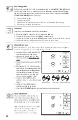
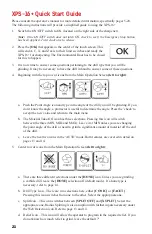
2.  Press the 

[OK]

 that appears in the center of the touch screen. This 

will send A, C, X, and Z axis to their limit switches and ready the 

XPS-16+ for sharpening. The Environmental Door has to be closed 

for this to happen.

3.  It is now time to answer some questions pertaining to the drill type that you will be 

grinding. It may be necessary to have the drill in hand to answer some of these questions.

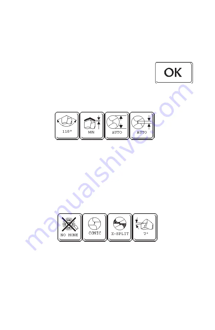
4.  Beginning with the top row of icons from the Main Operation Screen 

(left to right)

:

a.  Push the Point Angle icon and type in the angle of the drill you will be grinding. If you 

don’t know the angle, a protractor is useful to determine the angle. Press the ‘check’ to 

accept the new value and return to the main menu

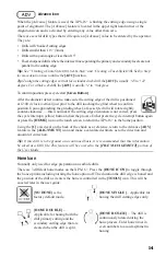
b.  The Material Take-Off icon has three selections. Pressing this icon will switch 

between the three (MIN, MID and MAX). Leave it at MIN unless you are changing 

the point angle of the drill or need to grind a significant amount of material off the end 

of the drill.

c. 

Leave the next two icons in the ‘AUTO’ mode. Both features are covered in detail on 

pages 13 and 14.

5.  Center row of icons from the Main Operation Screen 

(left to right)

:

a.  There are three different selections under the

 [HONE] 

icon. Unless you are grinding 

a carbide drill, leave the 

[HONE]

 selection off (default mode). If a hone type is 

necessary, refer to page 14. 

b.  Drill Type Icon – There are two selections here, either 

[CONIC]

 or 

[FACET]

Pressing this icon switches from one to the other. Select the appropriate one.

c.  Split Icon – This icon switches between 

[SPLIT OFF] 

and 

[X SPLIT]

. Select the 

appropriate one. Radius Splitting is also an option with further inputs necessary under 

the Web Detection icon. Refer to page 13 and 14.

d.  Relief Icon – This icon will allow the operator to program in the required relief. If you 

do not know how much relief to grind, leave the default 7°.

Содержание XPS-16+

Страница 1: ...Operating Instructions XPS 16 CNC Drill Grinder and Sharpener ...

Страница 2: ......

Страница 3: ... 6 Machine Axis Definition 8 Touch Screen Icon Reference 9 Touch Screen Details 11 XPS 16 Quick Start Guide 21 Creating a Conic Style Drill Step by Step 23 Creating a Facet Style Drill Step by Step 25 Copying a Drill Step by Step 27 Download Details 29 Advanced Sharpening Tips 31 General Maintenance 32 Troubleshooting 34 ...

Страница 4: ...hock Power tool plugs must match the outlet Never modify the plug in any way Do not use any adapter plugs with earthed grounded power tools Unmodified plugs and matching outlets will reduce risk of electric shock Avoid body contact with earthed or grounded surfaces such as pipes radiators ranges and refrigerators There is an increased risk of electric shock if your body is earthed or grounded Do n...

Страница 5: ...ective equipment such as dust mask non skid safety shoes hard hat or hearing protection used for appropriate conditions will reduce personal injuries Prevent unintentional starting Ensure the switch is in the off position before connecting to a power source Remove any adjusting key or wrench before turning the power tool on A wrench or a key left attached to a rotating part of the sharpener may re...

Страница 6: ...rce before making any adjustments changing attachments or storing the sharpener Such preventative safety measures reduce the risk of starting the sharpener accidentally Store idle power tools out of reach of children and do not allow persons unfamiliar with the sharpener or these operating instructions to operate the power tool Power tools are dangerous in the hands of untrained users Keep guards ...

Страница 7: ...ivities Wear protective clothing and wash exposed areas with soap and water Allowing dust to get into your mouth eyes or lie on the skin may promote absorption of harmful chemicals Safety Guidelines Definitions It is important for you to read and understand these Operating Instructions The information it contains relates to protecting YOUR SAFETY and PREVENTING PROBLEMS The symbols below are used ...

Страница 8: ...nd re locates the end of the drill ensuring an accurate split Specifications Standard Grinding Wheels 180 Grit CBN 220 Grit DIA Operating temperature Not less than 7 C 45 F or more than 32 C 90 F Motor Specs BLDC motor 115 230 V RPM 3800 4500 50 60 hz Power requirements 8 amp 115 V 4 amp 230 V Machine Dimensions 66cm W x 56cm D x 30 5cm H 26 W x 22 D x 12 H Machine Weight 52 kg 115lbs Shipping Dim...

Страница 9: ... Picture and Nomenclature Conic Drill Facet Drill Overall Length Length of Margin Flutes HelixAngle Lip ReliefAngle Across Margin Web Flute Length Land Width Shank Diameter Axis Length of Uncleared Flute Chisel Edge Web Land Lips Cutting Edges Margin Body Diameter Clearance Chisel Edge Angle Drill Diameter Point Angle Included ...

Страница 10: ... Split Diagram Facet Split Angle Diagram Relief Center of Split Diagram To Center To Center To Center Below Center Past Center Below Center Past Center Below Center Past Center 95 105 120 130 Excessive Relief Correct Relief Negative Relief ...

Страница 11: ...es the grinding wheel sideways C Axis A rotate stage which turns the drill bit about its axis AAxis A swing stage which tilts the drill bit up and down at the rear Z Axis An infeed axis which positions the drill bit closer to or further from the grinding wheel ...

Страница 12: ...le Stop Amber Continue Return to Home Point Angle Selection Minimal Material Removal Mid range Material Removal Primary and secondary cutting edge hone Hone primary cutting edge after sharpening Rotate drill in hone brush Maximum Material Removal Diameter Detection Auto Or Manual Tools Button To Access Second Page Touch Screen Icon Reference ...

Страница 13: ...xis Wheel Position Offset Wheel Edge Offset Adjustment X Axis Wheel Face Offset Adjustment Z Axis Split Point Offset Adjustment Position Stage For Belt Change Password Protected Area Drill Stick Out Adjustment To Adjust Facet Overlap File Management Sharpener Inches Active Sharpener mm Active Advance Selection Auto Mode Selector Manual Align Mode Selector Cancel Key Save Key Backspace Delete File ...

Страница 14: ... to the main operating screen Pressing the X button cancels the change and takes you back to main operating screen Touch Screen Details Main Operating Screen The screen shot this shows what will be depicted on the touch screen once power has been applied to the XPS 16 Press the check in order to initialize the XPS 16 This is the Main Operating Screen Starting left to right and top to bottom each i...

Страница 15: ...these features will be covered in the Web Detection section of the User Guide Tip The machine can be operated in either inches or millimeters To change between them press the INCH MM icon The value displayed on top in the bolder font is the current selection for all the applicable icons Material Removal Icon Each touch will change between three options Factory default is MIN Facet drill point is l...

Страница 16: ...e instances previously mentioned in the User Guide where the machine cannot make these calculations If these conditions occur the XPS 16 will interrupt the grind operation return to the home position and prompt the operator for the necessary information Press the OK icon on the touch screen to enter this feature or press the Alignment icon Web Thickness manual input In order to activate the Radius...

Страница 17: ... 22 degrees For a thick web drill the ADV is usually 2 to 8 degrees To confirm position press cycle start Green Button After the diameter detect routine make sure the cutting edge of the drill is positioned at 12 00 o clock vertical just prior to the drill touching the grind wheel to confirm position Upon approaching the grinding wheel a facet style drill will rotate slightly counter clockwise thi...

Страница 18: ... Facet Step by step instructions to sharpen each point style are on pages 20 and 21 Relief Adjustment Press the RELIEFADJUSTMENT icon to adjust relief from 5 18 accurate to 2 If the relief value specified is beyond the allow able range the XPS 16 with automatically default to its allowable range prior to sharpen ing Press the CHECK icon to accept the value or the X icon to exit to the Main user in...

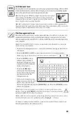
Страница 19: ...E icon Press the CHECK icon to remove the program Note In the event a program is over written a warning will show on the display Pressing the CHECK will allow the changes to the program and pressing the X will not allow the changes Note A drill file can be locked to avoid being edited or removed In order to do so start the drill file name with a plus symbol Example 135facet To delete or modify a l...

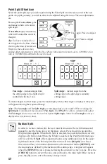
Страница 20: ...he X Split offset adjustments plus some additional ones In the upper right hand corner of the Point Split Offset menu will have R Split icon Press this icon to allow you to make adjustments to the amount of radius OFFSET and the stop angle as defined by the location of the cutting edge A keypad will appear when the OFFSET icon is pressed allowing the operator to enter a value Press the CHECK butto...

Страница 21: ...er facet is required add 010 or 1mm to the value Turn off the split feature and grind the drill If the results are acceptable save the drill file using the FILE MANAGEMENT icon the new drill stickout value will be saved as well If applicable remember to toggle the split feature on to the correct mode prior to saving the drill file To Center Below Center Past Center Tip The maximum amount of the ra...

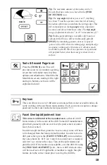
Страница 22: ...as it is used This screen allows the user to adjust the position of the drill in both the X and Z axis as it enters the hone Tip Adjustments are made in 1 1000 of an inch Normal offsets for the Hone will require more units of adjustment in order to see change Belt Change Icon In the event a spindle drive belt is compromised press the BELT CHANGE icon to move the grind motor to a position to access...

Страница 23: ...n the user presses the touch screen The adjustment amount is 1 to 60 seconds for all inputs After entering a value press the CHECK icon twice to return to the Main Menu screen Tip The longer the drill is introduced to the hone brush the larger the hone radius will be Trial and error is needed to determine a best cutting edge preparation for the drill s application Tip When using the provided Silic...

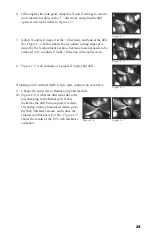
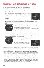
Страница 24: ...seful to determine the angle Press the check to accept the new value and return to the main menu b The Material Take Off icon has three selections Pressing this icon will switch between the three MIN MID and MAX Leave it at MIN unless you are changing the point angle of the drill or need to grind a significant amount of material off the end of the drill c Leave the next two icons in the AUTO mode ...

Страница 25: ...ock to 2 o clock Tighten the chuck knob clockwise While doing so be sure the tip of the drill is compressing the MTO plunger directly in front of the tip of the drill 3 Close the Environmental Door 4 Push the green Cycle Start button under the Emergency Stop button The Cycle Start button will illuminate for the entire sharpening cycle Note If the Environmental Door is not closed and or the MTO but...

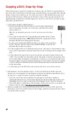
Страница 26: ...h the pattern drill If the pattern drill is not coolant fed attempt to copy the fan angle with the methods available to you By making the fan angle a little bigger than expecting how it will end up 65 instead of 55 the process will go faster because the sample will not have to be totally reground if the angles are wrong The angle between the cutting lips and the secondary cutting edges is called t...

Страница 27: ...e Radial split If this looks like the drill being copied it is done If wanting a more pronounced radius go to the Web Thickness screen and reduce the entered web thickness by 10 Figure C 7 shows the results of the 10 web thickness reduction If making a drill with a RADIUS style split continue on as follows 9 Change the split style to Radius and grind the drill Figure C 4 Figure C 5 Figure C 6 Figu...

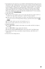
Страница 28: ...ey can be a good reference point since the fan angle can be increased or decreased to reveal or conceal more or less of the trailing edge of the coolant hole to match the pattern drill If the pattern drill is not coolant fed attempt to copy the fan angle with the methods available to you By making the fan angle a little bigger than expecting how it will end up 65 instead of 55 the process will go ...

Страница 29: ... pretty nice looking grind if wanting a generic radial point this one is good to go 11 Figure F 9 shows too much of a reduction in web thickness The ra dius is beginning to creep into the primary cutting edge and in another 10 would obliterate about half of it 8 If creating a radially split drill go ahead and change the split style to Radius and grind the drill 9 Figure F 6 is what the drill looks...

Страница 30: ...ne and it s important to remember that relief can only be measured at the margin of the drill e At the bottom left corner of the screen is the selector icon used to choose between the CBN wheel for HSS to Cobalt drills and the Diamond wheel for Carbide drills Pick the one that applies Remember the sharpener is relying on you to install the right wheel but doesn t know if you did Adjust the sharpen...

Страница 31: ...r settings 5 Setting Split Angles Tip Remember that the numbers used to set the Split Angle affect the settings available to build the Fan Angle Smaller Split Angle smaller Fan Angle available Tip Start with X and Z settings adjusted to the minus side and grind the drill If the angles are incorrect they can be changed without having to regrind the drill completely Save settings Tip Set the Split A...

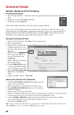
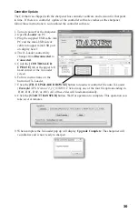
Страница 32: ...rpener 4 With the cable installed the X loader will display in the upper left hand corner Connected 5 Follow instructions at bottom of X Loader screen 6 Click the BROWSE button to create a destination folder to save the drill files to your PC 7 Click the START TRANSFER button to save to destination folder 8 A pop up window will say File Saved Sending Drill Files from PC to Sharpener 1 Click the SE...

Страница 33: ...ader connectivity changes from Disconnected to Connected 5 Click the CONTROLLER UPDATE tab at the upper left hand corner of the X Loader screen 6 Follow instructions on the bottom of X Loader 7 Click the FILE UPGRADE BROWSE button to load new controller file onto X Loader Example XPS Version 12_12_03 H00 Click on any one of the four file options ending in H00 H01 H02 or H03 All of these files will...

Страница 34: ...arly on in the sharpening process When developing a new drill point err on the material safe side when splitting Learn to use Single Point and Manual Alignment when needed especially for chisel edge placement A thick web drill requires less advance ADV 4 8º than a standard web ADV 14 18º To achieve desired radius in R Split slowly reduce Web Thickness In some cases it can be reduced by 65 of actua...

Страница 35: ...for cuts or tears Tip Do not use machine if hoses are damaged 1 Unplug vacuum from power source 2 Using a hex key wrench remove bolt and washer 3 Wearing protective gloves remove top cover of vacuum canister remove filter cartridge Appropriately dispose of used filter 4 Unthread plastic nut retaining bottom of vacuum canister remove bottom of vacuum canister 5 Clean out residual grinding dust from...

Страница 36: ...ning the drill measure the drills new length MTO should be approximately 005 007 5 If incorrect adjust using Wheel Offset screen Changing the Grind Motor Vacuum Fuses 1 Unplug AC power 2 Both sets of fuses are located on the back of the machine on the outside the electrical box panel near the cord receptacle 3 Fuse holder is spring loaded Using a flat head screwdriver press in and turn counter clo...

Страница 37: ...ore than 32 C 90 F Restore calibrations from locked area After pressing CYCLE START the machine does not move into the sharpening cycle Make sure drill has been loaded properly and sensor button has been depressed Close door Software has caused machine to hang up Turn machine off and then on again Cycle start switch needs replacement Drill rotates in front of fiber optic sensor failing to locate c...

Страница 38: ...bad Old software installed 15 error margin allowed Cutting edge is not positioned correctly at 12 00 after edge detection Chip on cutting edge Burr on cutting edge The fiber optic sensor has detected the split line as cutting edge Drill has a hook in the cutting edge use the Advance Screen to compensate Changing from extreme point angles Example Converting a 180 drill into a 118 point angle Materi...

Страница 39: ...k or on the body of the drill During initialization chuck tries to rotate unsuccessfully while making a ratcheting buzzing noise Solenoid has malfunctioned and chuck locking pin will not retract Solenoid fuse blown Drive pulley loose Belt condition Unexplained motion Machine temperature is too cold hot do not operate until machine temperature reaches 7 C 45 F but not more than 32 C 90 F Software i...

Страница 40: ...37 Notes ...

Страница 41: ...38 ...

Страница 42: ...Phone 800 597 6170 541 552 1301 Darex LLC PO Box 730 210 E Hersey St Ashland OR 97520 USA Fax 541 552 1377 Web www darex com PP12851KF Rev 0 6 14 ...

Отзывы: