10
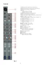
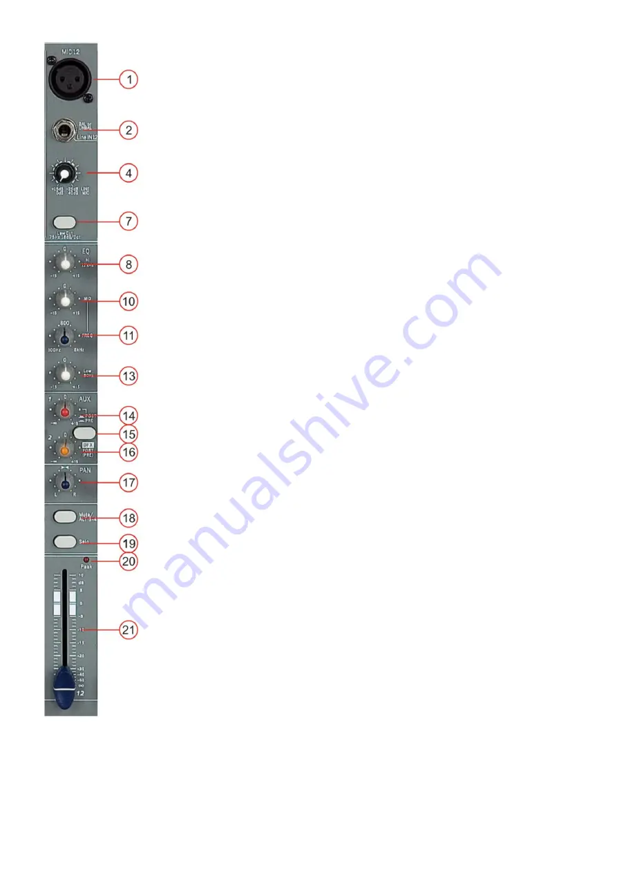
14 / 15/ 16 aux 1 / aux 2 DFX
The FX control allows you to change the aux 1 Level to the FX Mix. The pre/ post
switch toggles the aux 1 signal to be taken pre- or post- fader.
Using the aux 2/ DFX control lets you route the corresponding input signal to the
integrated digital effect unit at variable levels. In this way assigning special effects
to musical instruments or vocals is fairly simple. When making an effect-mix, it’s
advisable to start with all FX-controls set to their center position. You can further
increase or reduce the effect’s intensity, depending on your personal preferences.
Please make sure to carefully monitor the peak LED (25) in the DFX channel during
a performance.
17. Pan
By using the panorama control you can change the input signal’s position within
the stereo image. When the panorama control is set to center position, the audio
signal is equal for both the left and right output.
18. Main/ ALT 3-4
This button allows you to assign a channel to either the main mix or to ALT 3-4.
19. Solo
The Solo button (pre fade listening) is designed to select one channel and listen to
that channel only on your control room or phones output. You can choose to route
the Solo signal post or pre- fade by using the solo mode button.
20. PEAK Indicator
The peak indicator shows peak levels in a channel’s incoming signal level. If the
red peak LED frequently blinks or constantly lights, the corresponding channel is
likely to enter clipping and you have to reduce the input’s amplification using the
gain control. The peak LED lights at a level of 8 dB below clipping. Make sure that
the Peak LED lights only briefly during dynamic peaks.
21. Channel Fade
The fader
controls the volume of a single channel. The channel faders should be
positioned within the range of -5dB to 0dB, leaving you with sufficient room to allow
precise matching of differences in the channel’s level settings. The overall volume
is set with the master fader. Even though the channel faders offer an additional
gain of +10dB, it is better not to exceed the +5dB position.
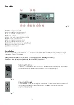
64. INSERT
Insert for external device, effect, compressor etc. The insert jack is situated at the
rear of the Sessionmix 12 DSP. It provides an output of the channels signal is
amplified to line-level. At the same time the inserts have an input at line level from
where the signal is further routed through the channels equalizer and so forth.
When not in use (unplugged), input and output are connected to provide normal
signal flow in that channel.
Fig. 9
Содержание Sessionmix 12 DSP
Страница 1: ...Sessionmix 12 DSP ORDERCODE D2193...
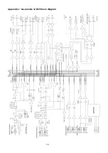
Страница 20: ...18 Appendix 1 Sessionmix 12 DSP block diagram...
Страница 21: ...2008 DapAudio...


