background image


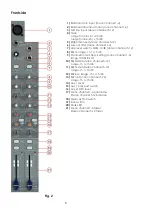
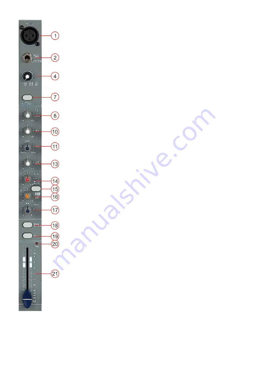
1. Mic 

Electronically balanced XLR-type inputs for connecting low-impedance 
microphones. The input provides extremely low noise and low hum signal 
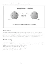
processing. When connecting a microphone make sure that the pin assignment is 
correct. Always make sure to read the manual of the microphone you want to 
connect. The XLR-inputs are not suitable for connecting line level signals like an 
additional mixing console, FX-unit, etc. You have to use the LINE-inputs, when 
connecting this kind of equipment.


2. Line 

Electronically balanced inputs for connecting a keyboard, CD player, mixer, etc. 
You can connect balanced or unbalanced signal sources to the Line input. Do not 
connect signal devices to a channel’s MIC and LINE input at the same time. This 
will cause mutual interference, which results in level reduction. 


Note: When connecting signal sources, please make sure that the corresponding 
channel faders and the master faders are at their minimum settings. Otherwise  
plug-in noise can occur. 


4. Gain 

Mic Channel input level is determined by the Gain control. With the Gain control  


you can adjust the MIC or LINE input-sensitivity, while optimally matching the 


incoming signals to the mixer’s internal operation level. The high gain of this mixer is 


ideal when dealing with very low input levels (i.e. vocal recordings or distant sound 


sources). 


How to set the Input level: 
1)

 Set the gain control and the corresponding channel fader to their minimum  


     setting. 

2)

 Connect the desired sound source (CD player, microphone, etc.) to the  


corresponding mic or line input. 

3)

 Play the sound source at its highest volume setting; respectively, sing or speak as  


loud as possible directly into the microphone. 

4)

 While doing so, adjust the input level using the gain control, so that during the  


loudest passages the peak LED is just not lit. 


This basic channel setting leaves you at least 8dB headroom. This means, you have 
at least 8dB before signal clipping. If you want to make further adjustments to the 
channel’s EQ setting, you should repeat step 

3

 and 

4

 again. 


7. Low cut switch 

If you push the “Low Cut” button, a filter will be inserted into the audio chain of the 
Sessionmix 12 DSP that has a characteristic 62Hz, 18dB/oct high pass characteristic 
to cut any undesired low frequencies. This function can be used to cut the 
humming sound or to prevent resonances of low frequencies, when the speakers 
are placed in close distance. 


8 / 10 / 13. Equalizer SECTION (HI / MID / LOW) 


The mixer’s Equalizer section allows shaping of the incoming audio signal. All mono 


input channels are fitted with 3-band EQ. The upper (8) and lower (13) shelving 


controls have their frequencies fixed at 12 KHz and 80 Hz respectively. The Mid  


range control (10) has a peaking response frequency at 2.5 KHz. All 3 bands have 


up to 15 dB cut and boost, with a centre detent for. Turning the Equalizer to 


Fig. 8


the right amplifies the frequency range, turning to the left attenuates the signal.  


Minor changes to the Equalizer control usually produce the best results. Try to avoid 


excessive enhancement of the MID band. 
 

11. Parametric Mid


This Control is for adjusting the filter frequency (100 Hz–8kHz) for the equalizer in the 
midrange 

Содержание Sessionmix 12 DSP

Страница 1: ...Sessionmix 12 DSP ORDERCODE D2193...

Страница 2: ...n DAP Audio for more excellent audio products We design and manufacture professional audio equipment for the entertainment industry New products are being launched regularly We work hard to keep you o...

Страница 3: ...12 DSP Product Guide Warning Safety instructions Operating Determinations Description Features Overview Frontside Backside Installation Set Up and Operation Connection Cables Maintenance Troubleshooti...

Страница 4: ...r or replace product s As a suggestion proper UPS packing or double boxing is always a safe method to use Note If you are given an RMA number please include the following information on a piece of pap...

Страница 5: ...Do not insert objects into air vents Do not connect this system to a dimmerpack Do not switch the system on and off in short intervals as this would reduce the system s life Do not open the device an...

Страница 6: ...e arising condensation water might damage your system Leave the system switched off until it has reached room temperature If your Dap Audio device fails to work properly discontinue use immediately Pa...

Страница 7: ...Tremelo Plate Leslie Vocal Rotary Small Room Flanger Verb Large Hall Extremely high headroom offering enough dynamic range Extra low distortion pre amp section Better performance with excellent noise...

Страница 8: ...o channel 5 12 8 EQ hi range 15 15 dB 9 Parametric mid freq Setting mono channel 1 4 range 100 Hz 8 kHz 10 EQ Hi Mid stereo channel 5 12 range 15 15 dB 11 EQ hi mid stereo channel 5 12 range 15 15 dB...

Страница 9: ...r LED 32 Aux 2 send 33 LED VU Meter 34 Level set 35 Solo active LED 36 Solo mode switch 37 Power on LED 38 Main mix select 39 ALT 3 4 select 40 2 TK in select 41 ALT 3 4 assign switch 42 2 TK assign s...

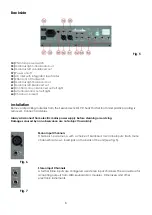
Страница 10: ...sionmix 12 DSP Check that all foam and plastic padding is removed Connect all cables Always disconnect from electric mains power supply before cleaning or servicing Damages caused by non observance ar...

Страница 11: ...CD player microphone etc to the corresponding mic or line input 3 Play the sound source at its highest volume setting respectively sing or speak as loud as possible directly into the microphone 4 Whi...

Страница 12: ...put You can choose to route the Solo signal post or pre fade by using the solo mode button 20 PEAK Indicator The peak indicator shows peak levels in a channel s incoming signal level If the red peak L...

Страница 13: ...e When making an effect mix it s advisable to start with all FX controls set to their center position You can further increase or reduce the effect s intensity depending on your personal preferences P...

Страница 14: ...ust the level of the aux send output Fig 12 31 Phantom Power LED This LED indicates when the phantom power is switched on for the microphone inputs After switching on the mixer the red LED should not...

Страница 15: ...vel of the DSP section by using the aux 2 send control Digital clipping is an effect you definitely will not like 26 Effect dial Use this dial for selecting an effect preset Push the dial for activati...

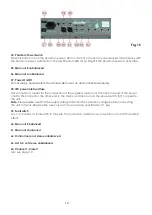
Страница 16: ...he connection of the supplied main cord Connect one end of the power cord to the connector the other end to the mains and then turn on the power switch 57 to operate the unit Note Please make sure tha...

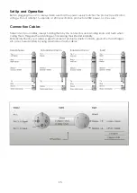
Страница 17: ...e versa Connection Cables Take care of your cables always holding them by the connectors and avoiding knots and twists when coiling them This gives the advantage of increasing their life and reliabili...

Страница 18: ...ectors are thoroughly dry before linking equipment or supplying electric power Troubleshooting DAP Audio Sessionmix 12 DSP This troubleshooting guide is meant to help solve simple problems If a proble...

Страница 19: ...dances Input impedance 10 kilo Ohm Out impedance 120 Ohm Tape out 1 kilo Ohm Equalization Hi shelving 15 dB 12 kHz Mid bell 15 dB 100 Hz 8 kHz Mic Ch 15 dB 3 kHz 500 Hz Stereo Ch Low shelving 15 dB 80...

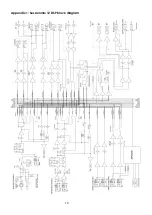
Страница 20: ...18 Appendix 1 Sessionmix 12 DSP block diagram...

Страница 21: ...2008 DapAudio...

Отзывы: