background image


DT-50 and DT-50A Tire Changer 

9


P/N 5900260 — Rev. A1 — Dec. 2020 

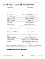
Specifications Model DT-50 and DT-50A 

Specification 

Performance 

Motor 

110/220 VAC, 50-60 HZ, 1 Ph., 1.1kW

*


Power Cord Length 

8 Ft. / 2438 mm 

Drive System Type 

Electric / Air 

Air Requirement 

116 – 145 PSI (8 – 10 BAR) at 15-25 CFM 

Wheel Clamping Method 

4 Clamps – Internal / External 

Table Clamping System 

Dual Pneumatic Cylinders 

Bead Breaking System 

Pneumatic Blade 

Tower Design 

Rigid Fixed / Swing Arm 

Assist Tower Design 

Swing Arm (Model DT-50A Only) 

Rim Size Clamping Min.-Max.

**


12-26 in. 

Actual Clamping Diameter Min.-Max. 

13.5-27.5 in. / 345-700 mm 

Turntable Rim Width Capacity 

3 – 15 in / 76 – 381 mm 

Bead Breaker Rim Width Capacity 

3 – 14 in / 76 – 356 mm 

Maximum Tire Diameter 

47 in / 1200 mm 

Noise 

<70 dB 

Operating Temperature 

+39˚ to +104˚F /+4˚ to +40˚C 

Operating Humidity 

90% at 20˚C and 50% at 40˚C Non-Condensing 

Dimensions 

50.78 in. wide by 47.25 in. deep by 76 in. high 

1290 mm wide by 1200 mm deep by 1930 mm 

high 

*

Factory configured for 110 VAC operation; may be switched to 220 VAC. Refer t

Connecting to 

Power

 for instructions; licensed, certified Electrician required to switch to 220 VAC. 

**

Rim size indicates the Bead Seat diameter 

not 

the outside diameter of the Wheel.


Specifications subject to change without notice. 


Содержание DT-50

Страница 1: ...rnia USA Made in China DANGER Read the entire contents of this manual before using this product Failure to follow the instructions and safety precautions in this manual can result in serious injury or...

Страница 2: ...nearest BendPak Dannmar dealer or visit Dannmar com support warranty Go to dannmar com support and fill out the online form to register your product be sure to click Submit Safety Your new product wa...

Страница 3: ...mandatory reading for all users of the DT 50 and DT 50A including anyone who sets up operates maintains or repairs it You can always find the latest version of the manual for your product on the Dannm...

Страница 4: ...he product until you are familiar with all operating instructions and warnings Do not allow anyone else to operate the product until they are also familiar with all operating instructions and warnings...

Страница 5: ...Calls attention to a hazard that will result in death or injury WARNING Calls attention to a hazard or unsafe practice that could result in death or injury CAUTION Calls attention to a hazard or unsaf...

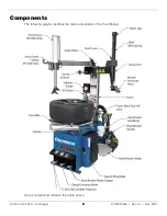
Страница 6: ...DT 50 and DT 50A Tire Changer 6 P N 5900260 Rev A1 Dec 2020 Components The following graphic identifies the main components of the Tire Changer Not all components visible in the photo above...

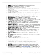
Страница 7: ...a burst of air pressure to help seat a difficult Bead Never point the Turbo Blast Nozzle at people or things use it with caution Use it only to seat a difficult Bead nothing else Has a Shut off Valve...

Страница 8: ...ould be released all at once possibly injuring or in rare cases killing the Operator or bystanders Q What important thing should I always do when working with the Tire Changer A You must identify and...

Страница 9: ...2 26 in Actual Clamping Diameter Min Max 13 5 27 5 in 345 700 mm Turntable Rim Width Capacity 3 15 in 76 381 mm Bead Breaker Rim Width Capacity 3 14 in 76 356 mm Maximum Tire Diameter 47 in 1200 mm No...

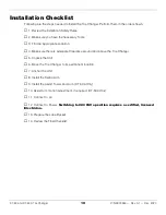
Страница 10: ...priate Location 4 Make sure there is adequate Clearance around and above the Tire Changer 5 Unpack the Unit 6 Move the Tire Changer to its permanent location 7 Anchor the Unit 8 Install the Swing Arm...

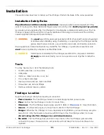
Страница 11: ...N Certain parts of installing the Tire Changer are difficult for one person Dannmar strongly recommends having two or more persons work together to install the unit Tools You may need some or all of t...

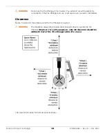
Страница 12: ...Changer and you could electrocute yourself or bystanders Clearance Space to work and move tires around the Tire Changer is required WARNING The Clearance values shown below allow enough space to opera...

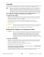
Страница 13: ...t the Cover off CAUTION Dannmar recommends having at least two people lift the Cover off it is heavy and awkward If the cover is dropped it could cause injury or equipment damage Remove the plastic wr...

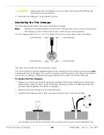
Страница 14: ...Not all components shown The Anchor Bolts sometimes called Wedge Anchors mentioned in the following procedure are not supplied with the Tire Changer You could for example use 3 8 in wide by 3 in deep...

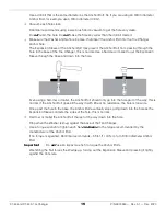
Страница 15: ...ase and down into the hole Even using a hammer or mallet the Anchor Bolt should only go into the hole part of the way this is normal If the Anchor Bolt goes all the way in with little or no resistance...

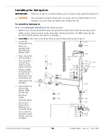
Страница 16: ...ipment leather gloves steel toed work boots back belts hearing protection and ANSI approved eye protection safety glasses face shield or goggles Carefully remove the components that secured the Swing...

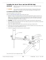
Страница 17: ...rm Make sure you are wearing OSHA approved publication 3151 Personal Protective Equipment leather gloves steel toed work boots back belts hearing protection and ANSI approved eye protection safety gla...

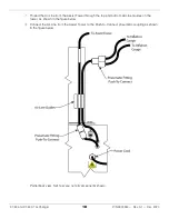
Страница 18: ...e from the Assist Tower through the top and bottom Air Line Guides on the tower as shown in the figure below Connect the Air Line from the Assist Tower to the Push to Connect pneumatic coupling as sho...

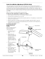
Страница 19: ...or the Assist Arm Tower Pivot Point Loosen the Top Lock Nut by one or two turns Slowly loosen the Bottom Lock Nut while moving the Assist Arm The resistance to motion should reduce as you loosen the n...

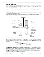
Страница 20: ...urce connects to the Tire Changer via the Air In connector on the Regulator Filter Note You need to provide a Fitting for the Air In connector it is not supplied Side view Drawing not to scale Not all...

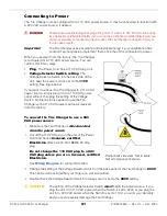
Страница 21: ...hanger to a 110 VAC power source simply plug it in to a 110 VAC power outlet without changing the setting of the Voltage Switch No Electrician is needed to use the Tire Changer with a 110 VAC power so...

Страница 22: ...recessed area or below floor level Preparing the Lube Bucket The Tire Changer comes with a Lube Bucket to hold Lube and a Lube Brush to apply Lube Dannmar does not include Lube with the Tire Changer...

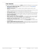
Страница 23: ...ot Pedal to check for electric power If the Turntable turns you have power Check the Anchor Bolts If the Tire Changer is bolted down make sure the Anchor Bolts are in position and tightened down Make...

Страница 24: ...allowed inflation pressure it should be marked on the sidewall of the Tire Do not exceed the maximum allowed inflation pressure of the Tire Make sure the Tire is restrained for inflation by either in...

Страница 25: ...ion cord so that it will not be tripped over or pulled out Do not use anything flammable on the Beads or Rims as lubrication Use non flammable vegetable or soap based rubber lubricant Do not use the T...

Страница 26: ...Foot Pedal Clamp Mechanism The Clamp Mechanism moves in and out to clamp Wheels either externally or internally All four Clamp Mechanisms move together They can all be in or they can all be out Exter...

Страница 27: ...The Tire Changer has Three Foot Pedals that control the Tire Changer actions Turntable Foot Pedals rotate the Turntable Press and hold Down the Turntable Foot Pedal to rotate clockwise press and hold...

Страница 28: ...e Valve Releases air from a Tire WARNING Do not hold the Air Chuck while you are inflating a Tire This leaves you too close to the Tire which could result in injury if there is a problem during inflat...

Страница 29: ...rol Limits how far the Swing Arm can move back which lets you position it exactly when you get it to the desired location Useful if you are going to be working on multiple Wheels that are the same siz...

Страница 30: ...goes over the Demount Lip and under the Mount Lip During mounting The Tire Bead goes over the Mount Lip and under the Demount Lip The Mount Demount Head that comes with the Tire Changer is alloy stee...

Страница 31: ...two Tools that may be attached to the Assist Tower Assist Tower Block Used to hold down the Top Bead during the mounting demounting process Restraint Tool This Tool slides onto the Assist Tower Block...

Страница 32: ...nger head See figure to the right The Assist Tower can be used to push down on the top Bead while the Tire Mount Demount Head uses a Tire Compression Roller The compression roller presses down on the...

Страница 33: ...aker Foot Pedal The main parts of the Bead Breaker are Bead Breaker Mechanism Moves in and out under the control of the Bead Breaker Foot Pedal Moves with great force make sure you are completely clea...

Страница 34: ...significantly increase the chances of damaging the Wheel and the Tire Tire Lubricant is not provided with the Tire Changer Check for damage Especially with expensive Wheels make sure to check them for...

Страница 35: ...do attempt to demount or mount this type of Wheel proceed with extreme caution European Performance Wheels Some European performance Wheels have very large humps except near the Valve Hole On these Wh...

Страница 36: ...ire This is called Breaking the Bead Use care when Breaking the Bead of Wheels with a Tire Pressure Monitoring System TPMS Secure the Wheel on the Turntable It is important for the Wheel to stay in pl...

Страница 37: ...be done after the old Tire has been demounted but before the new Tire is mounted Use a Valve Stem Installer Remover Tool sometimes called a Valve Stem Puller Remover Tool that can be used to both rem...

Страница 38: ...ore Tool to remove the Valve Core Do not risk damaging the valve core or the stem by using the wrong tool If you are going to use the same Valve Stem with the new Tire you are going to mount keep the...

Страница 39: ...NSI approved eye protection safety glasses face shield or goggles Check the Tire again to make sure it is fully deflated Check both sides of the Tire to make sure all Wheel weights from previous balan...

Страница 40: ...veral attempts to fully break the Bead When the Bead is broken at the current location rotate the Tire 180 and break the Bead at that location Important Every Tire is different With some Tires the ent...

Страница 41: ...and ANSI approved eye protection safety glasses face shield or goggles Identify the Narrow side of the Tire this side goes up Determine which clamping method you are going to use If you are clamping e...

Страница 42: ...To demount a Tire Make sure you are wearing OSHA approved publication 3151 Personal Protective Equipment leather gloves steel toed work boots back belts hearing protection and ANSI approved eye protec...

Страница 43: ...fting Tool at this point it could easily injure the Operator or damage the Wheel Tire or the Tire Changer Check to make sure the Bead Lifting Tool is lifting the Tire Bead up and over the Demount Lip...

Страница 44: ...ifting Tool The top Bead is demounted The next step is to demount the bottom Bead over the top Rim Make sure there is still lubricant on the bottom Bead and the top Rim If there is not put some more o...

Страница 45: ...ou have positively identified and correctly matched the Tire and Rim diameters If you try to seat a Tire Bead on a mismatched Wheel and Tire by inflating it the Tire Bead may break with explosive forc...

Страница 46: ...nally or externally Apply Tire lubricant to the top and bottom Beads and the top Rim Put the Tire over the Wheel with the side that will be next to the Mount Demount Head low and the other side high a...

Страница 47: ...the Turntable clockwise If using the Bead Lifting Tool to hold down the Sidewall starting near the Mount Demount Head move it around with the Tire as it rotates If you run into any difficulty as the T...

Страница 48: ...t use a Tire Inflation Cage such as the RIC 4716 for safety purposes If a Tire fails at high pressure it can explode and cause serious injury or death to anyone near it Using a Tire Inflation Cage hel...

Страница 49: ...eration can create a significant noise level during operation and compressed air can dislodge debris that can damage your eyes If the Bead is still not sealed turn on the Turbo Blast valve Position th...

Страница 50: ...Bead Seating usually requires 7 psi or above Some Beads are hard to seat but never exceed 40 psi to seat the Bead If air pressure in the Tire gets to 40 psi but the Beads are still not seated use the...

Страница 51: ...amping interferes with inflation Instead switch to internal clamping or restrain the Tire in an Inflation Cage DT 50A only may use the Assist Tower with Restraining Block to restrain the Tire on the T...

Страница 52: ...Oiler Lubricator It should be 1 to 2 drops per use of a pneumatic component If it is above or below this level you need to adjust it Refer to Check the Oil Feed Rate and Adding Oil for instructions W...

Страница 53: ...prevent the water from escaping into the Tire Changer To drain water from the Regulator Filter reservoir Check the Water Sight Gauge to see how much water is currently in the reservoir If the reservoi...

Страница 54: ...vide one or two drops of oil per clamp activation If you are getting fewer than 1 or 2 drops turn the Adjustment Screw counter clockwise using a small flat head screwdriver then press the Clamps In or...

Страница 55: ...e electrical path from the supplied cord to the power source If any issues are found have them repaired Foot pedals fail to reset after depressing Return spring is worn damaged or broken Replace sprin...

Страница 56: ...e is out of adjustment Loosen the bolts of the locking plate and readjust The shaft locking plate is worn Replace the locking plate The Inflation Gauge is not working correctly Check the accuracy of t...

Страница 57: ...DT 50 and DT 50A Tire Changer 57 P N 5900260 Rev A1 Dec 2020 Wiring Diagram...

Страница 58: ...DT 50 and DT 50A Tire Changer 58 P N 5900260 Rev A1 Dec 2020 Labels...

Страница 59: ...DT 50 and DT 50A Tire Changer 59 P N 5900260 Rev A1 Dec 2020 A B C D Model DT 50A Only Model DT 50 Only...

Страница 60: ...DT 50 and DT 50A Tire Changer 60 P N 5900260 Rev A1 Dec 2020...

Страница 61: ...102 BB Arm Shaft Baffle 103 SHCS M6x16 5400913 104 Washer 6 105 Spring Washer 6 106 Eccentric Bushing 107 Metal Bushing 108 SHCS M12x35 109 Spring Washer 12 110 BB Arm Shock 5327530 111 STS M5 5 X 25...

Страница 62: ...X12 137 Cross Recessed Round Head Screw M6X20 138 Pad 6 139 HHB 140 Washer 141 SHCS M6x16 5400913 142 Washer 6 143 Spring Washer 6 144 SHCS M4x50 5327444 145 Voltage Selector Switch 146 Terminal Block...

Страница 63: ...63 P N 5900260 Rev A1 Dec 2020 Tower Tower Parts List Part Number Item Description 201 Fitting Straight 8 8 G1 4 202 Tower Unit Weldment 5327449 203 Pressure Release Valve 5401222 204 Swing Arm Adjus...

Страница 64: ...Swing Arm Swing Arm Parts List Part Number Item Description 5400942 301 SHCS M10x25 302 Hex Shaft Cap 303 Hex Shaft Lock Cover 304 Hexagon Socket Head Screw M6x12 305 Hex Shaft Spring 306 Vertical Sh...

Страница 65: ...ng Head 5327636 323 Roller Insert 324 Ingot Screws 5327468 325 Hexagon Socket Set Screw With Flatpoint M12X16 5328119 326 Duckhead Insert 327 SHCS M8x25 5327436 328 Duckhead Retaining Washer 329 Sprin...

Страница 66: ...r Release Valve 404 Inflation Gauge 140psi 405 Inflation System Plastic Cover 5327484 406 Coiled Hose 5327538 407 Air Chuck 8 408 Block G1 8 409 Air Chuck I Models G1 4 G1 8 5327558 410 Fitting 8mm 53...

Страница 67: ...ntable Assy 504 Slide Shim Adjustment 5400905 505 Snap Ring 12 506 Slide Guide 5327735 507 Square Turntable Slide Rod Pad 5327500 508 Square Turntable Shaft Sleeve 509 Spring Washer 12 510 HHB M12x50...

Страница 68: ...Dec 2020 Square Turntable Assy Square Turntable Assy Parts List Part Number Item Description 601 Square Turntable Main Board 602 Square Turntable Spacer 603 Square Turntable Link 5327521 604 Square Tu...

Страница 69: ...ylinder Cover 5327494 703 Y Ring 32x20x6 704 HHB 705 Nut M8 5327486 706 O Ring 16x2 4 707 Small Cylinder Piston 708 Washer 12 709 Nut M12 710 Small Rear Cylinder Cover 5327489 711 O Ring 75x5 7 712 Un...

Страница 70: ...ing Washer 6 5400913 805 Washer 6 5327682 806 Y Ring 200x12x6 807 O Ring 195x5 9 5327413 808 BB Cylinder Piston 5327537 809 O Ring 193x5 7 810 BB Cylinder Rod 5401520 811 Big cylinder Flange Unit Weld...

Страница 71: ...eaker Bracket Parts List Part Number Item Description 901 Bead Breaker Arm 902 Bead Breaker Arm Pivot Pin 903 Seeger Ring 35 904 Curved Spring Washers 16 5327609 905 SHCS M14x95 906 Spring Washer 14 9...

Страница 72: ...Bowl 1005 Plastic Quick Release Valve Body 5327561 1006 Copper Silencer 1007 Fitting 10 G1 4 1008 Quick Release Valve Section Quick Release Valve Section B Quick Release Valve Section B Parts List Par...

Страница 73: ...DT 50 and DT 50A Tire Changer 73 P N 5900260 Rev A1 Dec 2020 Gearbox...

Страница 74: ...ge 1204 SHCS M8x30 1205 Bearing 1206 Cone Shaft 1207 Turbine Key 14x8x40 1208 Turbine 1209 Oil Block 1210 Cone Roller Bearing 1211 Gear Stud 1212 Turbine Key 6X6X20 5545202 1213 Gear Stud Pad 1214 SHC...

Страница 75: ...itch 1302 Directional Switch Bracket 1303 Spring Washer 5 5400913 1304 Washer 6 1305 Cross recessed round head screw M5X16 5400324 1306 Turntable Direction Switch Cam 1307 Cross recessed round head sc...

Страница 76: ...ldment 5400249 1322 Rubber washer 1323 Pad 10 1324 Rubber washer 5327185 1325 Motor 1326 Start capacitor 5327819 1327 Capacitor 1328 Motor Assy 1329 Turntable Direction Switch Assy Rotary Valve Rotary...

Страница 77: ...Item Description 1501 Shaft Ring 12 1502 Washer 12 1503 Lock Nut M8 1504 Foot Pedal 1505 Washer 8 1506 Foot Pedal Shaft 1507 Baseplate Assembly Welding Piece 1508 CAM Connecting Rod 1509 SHCS M6x16 1...

Страница 78: ...ir Valve O Ring Spacer 1523 Cam Spacer 1524 Cross Recessed Head Tapping Screw 4 2X12 1525 Cam Cover 1526 Washer 10 1527 Split Pin 1528 Air Valve Connecting Link 1529 Air Valve End Cap 1530 Silencer G1...

Страница 79: ...e Connector 5328444 1605 White Steel Buckle 1606 PU Straight Pipe 1607 PVC Steel Wire Tube 1608 Nylon Sleeve 5328443 1609 Turbo Blast Handle 1610 Locknut Elbow 1611 Union 1612 Clamp Nut 1613 Vent Valv...

Страница 80: ...s Recessed Round Head Screw M6X12 1705 Pedal Valve Unit Weldment 1706 Bead Blaster Valve Assembly 5327821 1707 O Ring 15 4X3 9 1708 Air Valve End Cap 15X1 2 1709 Air Valve O Ring Spacer 1710 Bead Blas...

Страница 81: ...Inflation Foot Pedal Lever Link 5400457 1726 Nut M10 X 1 5 NL 1727 Washer 8 1728 Foot pedal 1729 Open straight pin 4X18 1730 Washer 8 1731 Socket head cap screw M8X20 1732 Washer 8 1733 Inner hexangul...

Страница 82: ...35x3 1 1808 O Ring 84x3 1 1809 Cylinder Connecting Bolt 1810 Banjo Bolt G1 8 6 Single 1811 Cylinder Front Plate 1812 Cylinder 1813 Cross Recessed Pan Head Screw M5X12 1814 Brass Cap 1815 Bearing 1816...

Страница 83: ...DT 50 and DT 50A Tire Changer 83 P N 5900260 Rev A1 Dec 2020 Maintenance Log...

Страница 84: ...1645 Lemonwood Drive Santa Paula CA 93060 USA 2020 Dannmar Inc All rights reserved Dannmar com...

Отзывы: