


VLT
®
2800 Series
Please contact your Danfoss supplier for
further information.
■
D.C. injection braking
If the three-phase winding of the stator is fed with
direct current, a stationary magnetic field will be
set up in the stator bore causing a voltage to be
induced in the bars of the cage rotor as long as
the rotor is in motion. Since the electrical resistance
of the rotor cage is very low, even small induced
voltages can create a high rotor current. This current
will produce a strong braking effect on the bars
and hence on the rotor. As the speed falls, the
frequency of the induced voltage falls and with it the
inductive impedance. The ohmic resistance of the
rotor gradually becomes dominant and so increases
the braking effect as the speed comes down. The
braking torque generated falls away steeply just before
standstill and finally ceases when there is no further
movement. Direct current injection braking is therefore
not suitable for actually holding a load at rest.
■
AC-braking
When the motor acts as a brake the DC-link voltage
will increase because energy is fed back to the
DC-link. The principle in AC-brake is to increase the
magnetisation during the braking and thereby increase
the thermal losses of the motor. Using par. 144 in VLT
2800 it is possible to adjust the size of the generator
torque that can be applied to the motor without the
intermediate circuit voltage exceeding the warning level.
The braking torque depends on the speed. With
the AC-brake function enabled and parameter 144
= 1,3 (factory setting) it is possible to brake with
about 50 % of rated torque below 2/3 of rated speed
and with about 25 % at rated speed. The function
is not working at low speed (below 1/3 of nominal
motor speed). It is only possible to run for about 30
seconds with parameter 144 greater than 1.2.
NB!:
If the value in parameter 144 is increased,
the motor current will simultaneously increase
significantly when generator loads are applied.
The parameter should therefore only be changed if
it is guaranteed during measurement that the motor
current in all operating situations will never exceed the
maximum permitted current in the motor. Please note:
The current can not be read out from the display.
■
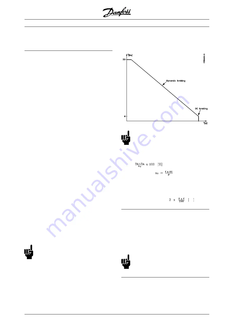
Optimal braking using resistor
Dynamic braking is useful from maximum speed
down to a certain frequency. Below this frequency
DC braking is to be applied as required. The most
efficient way of doing this is by using a combination of
dynamic and DC braking. See the illustration.
NB!:
When changing from dynamic to DC braking,
there will be a short period (2-6 milliseconds)
with very low braking torque.
How to calculate optimum DC-brake cut in frequency:
Slip S=
Synchronous speed
[1/min]
f = frequency
p = no.
of pole pairs
n
n
= speed of the rotor
DC-brake cut in frequency =
Hz
■
Brake cable
Max. length [m]: 20 m
The connection cable to the brake resistor must
be screened/armoured. Connect the screen
to the conductive backplate at the frequency
converter and to the brake resistor metal cabinet
by means of cable clamps.
NB!:
If Danfoss brake resistors are not used, it
must be ensured that the brake resistor
is induction-free.
MG.28.E9.02 - VLT is a registered Danfoss trademark
26


