


9
MG.10.P2.22 - VLT is a registered Danfoss trademark
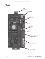
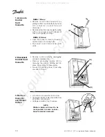
Installation
The following section describes the
installation procedures for the Modbus RTU
option card. For additional information on
installation and operation of the VLT 6000,
refer to the
VLT
6000 Operating Instructions
.
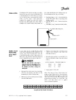
VLT adjustable frequency drive
contains dangerous voltages
when connected to line voltage.
After disconnecting from power
line, wait at least 14 minutes
before touching any electrical
components.
Only a competent electrician
should carr y out electrical
installation. Improper installation
of motor or drive can cause
equipment failure, serious injury
or death. Follow this manual,
National Electrical Codes and
local safety codes.
CAUTION
!
CAUTION
!
Electronic components of
adjustable frequency drive and
Modbus RTU option card are
sensitive to electrostatic
discharge (ESD). ESD can reduce
performance or destroy sensitive
electronic components. Follow
proper ESD procedures during
installation or servicing to prevent
damage.
It is responsibility of user or
installer of VLT adjustable
frequency drive to provide
proper grounding and motor
overload and branch protection
according to National Electrical
Codes and local codes.
Modbus RTU
Option Card
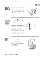
Environmental
Requirements
Environmental requirements for the Modbus
RTU option card are listed below.
Description
Requirement
Operating temperature
-5
°
F to +140
°
F (-20
°
C to +60
°
C)
Storage temperature
-40
°
F to +176
°
F (-40
°
C to + 80
°
C)
Humidity
5% to 95% relative, non-condensing
DANGER
!
WARNING
!
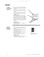
Power
Supply
The Modbus RTU option card is powered by
24 VDC and draws 38 mA of current at 24V.
All manuals and user guides at all-guides.com


