Application guidelines
36
FRCC.PC.021.A5.22
System design recommendations
A LLSV may be used to isolate the liquid charge
on the condenser side, thereby preventing
against charge transfer or excessive migration to
the compressor during off-cycles. The quantity of
refrigerant on the low-pressure side of the system
can be further reduced by using a pump-down
cycle in association with the LLSV.
Liquid line solenoid valve (LLSV)
Pump-down cycle
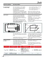
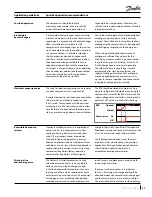
A pump-down cycle represents one of the most
effective ways to protect against the off-cycle
migration of liquid refrigerant. Once the system
has reached its set point and is about to shut
off, the LLSV on the condenser outlet closes.
The compressor then pumps the majority of
the refrigerant charge into the condenser and
receiver before the system stops on the low
pressure pump-down switch. This step reduces
the amount of charge on the low side in order to
prevent off-cycle migration. The recommended
low-pressure pump-down switch setting is
22 psig below the nominal evaporating pressure.
It shall not be set lower than 25 psig. For
suggested wiring diagrams, please see section
“Suggested wiring diagrams”.
Tests for pump down cycle approval
:
• As the pump-down switch setting is inside the
application envelope, tests should be carried
out to check unexpected cut-out during
transient conditions (ie. defrost – cold starting).
When unwanted cut-outs occur, the low
pressure pump-down switch can be delayed. In
this case a low pressure safety switch without
any delay timer is mandatory.
• While the thermostat is off, the number of
pressure switch resets should be limited to
avoid short cycling of the compressor. Use
dedicated wiring and an additional relay which
allows for one shot pump-down.
The pump-down allows to store all the refrigerant
in the high pressure side circuit. On unitary
or close-coupled systems, where the system
refrigerant charge is expected to be both correct
and definable the entire system charge may be
stored in the condenser during pump-down if all
components have been properly sized.
Other application needs a liquid receiver to store
the refrigerant.
Receiver dimensioning requires special attention.
The receiver shall be large enough to contain
part of the system refrigerant charge but it shall
not be dimensioned too large. A large receiver
easily leads to refrigerant overcharging during
maintenance operation.
Liquid flood back
During normal operation, refrigerant enters the
compressor as a superheated vapour. Liquid
flood back occurs when a part of the refrigerant
entering the compressor is still in liquid state.
Danfoss PSH scroll compressors can tolerate
occasional liquid flood back. However system
design must be such that repeated and excessive
flood back is not possible.
A continuous liquid flood back will cause oil
dilution and, in extreme situations lead to lack
of lubrication and high rate of oil leaving the
compressor.
Liquid flood back test
- Repetitive liquid
flood back testing must be carried out under
expansion valve threshold operating conditions:
a high pressure ratio and minimum evaporator
load, along with the measurement of suction
superheat, oil sump temperature and discharge
gas temperature.
During operations
, liquid flood back may be
detected by measuring either the oil sump
temperature or the discharge gas temperature.
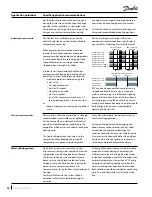
If at any time during operations, the oil sump
temperature drops to within 18°F or less above
the saturated suction temperature, or should
the discharge gas temperature be less than 63°F
on
off
Compressor 3
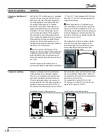
After 3 or 4 jogs the compressor can be started.
Then, optimum management of the Surface
Sump Heater (SSH) is provided by the operating
Control System (OCS).
Содержание PSH051-4
Страница 1: ...Danfoss scroll compressors PSH051 to 077 50 60 Hz R410A Application guidelines http danfoss us com...
Страница 2: ......
Страница 3: ......
Страница 58: ......
Страница 59: ......

