background image

Instructions

4 | AN18658643414604-001401 - 118U3276C

© Danfoss | DCS (CC) | 2020.06

itself is not a ”unit” in the scope this directive. 

 •  It is recommended to install the unit on rubber 

grommets or vibration dampers (not supplied).

  •  It is possible to stack units on top of each other.

Unit

Maximum 

stacking

Housing 1 

(Code no. 114X31-- or 114X41--)

3

Housing 2 

(Code no. 114X32-- or 114X42--)

2

Housing 3 

(Code no. 114X33-- or 114X43--)

2

Housing 4

(Code no. 114X34-- or 114X44--)

2

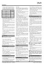
  •  When stacking, the topmost unit must be secu-

red to the wall, as shown in picture 2.

 •  Slowly release the nitrogen holding charge 

through the schrader port.

 •  Connect the unit to the system as soon as pos-

sible to avoid oil contamination from ambient 
moisture.

 •  Avoid material entering into the system while 

cutting tubes. Never drill holes where burrs 
cannot be removed.

 •  Braze with great care using state-of-the-art 

technique and vent piping with nitrogen gas 
flow.

 •  Connect the required safety and control de-

vices. When the schrader port is used for this, 
remove the internal valve.

  •  It is recommended to insulate the suction pipe 

up to the compressor inlet with 19 mm thick 
insulation.

5 – Leak detection

 Never pressurize the circuit with oxygen or dry 

air. This could cause fire or explosion.

  •  Do not use dye for leak detection.
 •  Perform a leak detection test on the complete 

system.

  •  The maximum test pressure is 31*

)

 bar.

 •  When a leak is discovered, repair the leak and 

repeat the leak detection.

*

)

 25 bar for OP-.......AJ.... & OP-.......FH.... models

6 – Vacuum dehydration

 •  Never use the compressor to evacuate the sys-

tem.

 •  Connect a vacuum pump to both the LP & HP 

sides.

 •  Pull down the system under a vacuum of 500 

µm Hg (0.67 mbar) absolute.

 •  Do not use a megohmmeter nor apply power 

to the compressor while it is under vacuum as 
this may cause internal damage.

7 – Electrical connections

  •  Switch off and isolate the main power supply.
 •  Ensure that power supply can not be switched 

on during installation.

 •  All electrical components must be selected as 

per local standards and unit requirements.

 •  Refer to wiring diagram for electrical connec-

tions details.

 •  Ensure that the power supply corresponds to 

the unit characteristics and that the power sup-
ply is stable (nominal voltage ±10% and nomi-
nal frequency ±2,5 Hz).

 •  Dimension the power supply cables according 

to unit data for voltage and current.

 •  Protect the power supply and ensure correct 

earthing. 

  •  Make the power supply according to local stan-

dards and legal requirements.

 •  The unit is equipped with an electronic control-

ler. Refer to Manual RS8GDxxx for details.

 •  

P02 version models (OP-xxxxxxxxxP02E) are 
equipped with Electronic circuit board (Module 
B Plus). Refer to section " Module B Plus User 
Guide " of this manual.

 •  The unit is equipped with a main switch with 

overload protection. The overload protection is 
factory preset but it is recommended to check 
the value before taking the unit in operation. 
The value for the overload protection can be 
found in the wiring diagram in the front door of 
the unit.

 •  The unit is equipped with high and low pres-

sure switches, which directly cut the power 
supply to the compressor in case of activation. 
Parameters for high and low pressure cut outs 
are preset in the controller, adapted to the com-
pressor installed in the unit.

 •  

P05 models are also equipped with phase 
sequence relay to protect the unit against 
phase loss/sequence/ asymmetry and under-/
over-voltage.

For units with a 3-phase scroll compressor (OP-
MPXMxxxxxxxxE), correct phase sequence for 
compressor rotation direction shall be observed.
 •  Determine the phase sequence by using a 

phase meter in order to establish the phase 
orders of line phases L1, L2 and L3.

  •  Connect line phases L1, L2 and L3 to main swit-

ch terminals T1, T2 and T3 respectively.

8 – Safety

Fusible Plug is not installed in unit, it is replaced 
with adapter blanking plug. 
Unit has liquid receiver with an Adapter Plug with 
3/8” NPT connection. installer/end user can select 
various options as mentioned in EN378-2 : 2016 
Article § 6.2.2.3
  •  The unit/installation into which the condensing 

unit is mounted/integrated, must be in accor-
dance with the PED.

  •  Beware of extremely hot and cold components.
 •  Beware of moving components. Power supply 

should be disconnected while servicing.

9 – Filling the system

 •  

Never start the compressor under vacuum. 
Keep the compressor switched off.

 •  Use only the refrigerant for which the unit is 

designed for.

 •  Fill the refrigerant in liquid phase into the 

condenser or liquid receiver. Ensure a slow 
charging of the system to 4 – 5 bar for R404A/ 
R448A/R449A/R407A/R407F/R452A and ap-
prox. 2 bar for R134a and R513A.

 •  The remaining charge is done until the instal-

lation has reached a level of stable nominal 
condition during operation.

 •  Never leave the filling cylinder connected to 

the circuit.

10 – Setting the electronic controller

 •  The unit is equipped with an electronic control-

ler which is factory programmed with parame-
ters for use with the actual unit. Refer to Manual 
RS8GDxxx for details.

 •  

By default, the electronic controller display 
shows the temperature value for the suction 
pressure in °C. To show the temperature value for 
the condensing pressure, push the lower button 
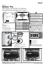
(picture 3).

The electronic controller is factory preset for R404A 
or R449A or R452A or R134a depending on the mo-
del of compressor mounted and application (Refer 
Annexx in Optyma Controller installation manual). 
If another refrigerant is used, the refrigerant setting 
must be changed. Parameter r12 must be set to 0 
before (software main switch= off).
 •  Push the upper button for a couple of seconds. 

The column with parameter codes appears.

 •  Push the upper or lower button to find parame-

ter code o30.

 •  Push the middle button until the value for this 

parameter is shown.

  •  Push the upper or lower button to select the new 

value: 2 = R22, 3 = R134a, 36 = R513A, 17 = R507, 
19 = R404A, 20 = R407C , 21 = R407A, 37 = R407F, 
40 = R448A, 41 = R449A, 42 = R452A.

 •  Push the middle button to confirm the selected 

value.

 For P02 version models (OP-xxxxxxxxxP02E), 

if o30 value is 19= R404A or 40=R448A or 
41=R449A in controller, 
 •  Push the upper or lower button to find parame-

ter code r84. 

 •  Push the middle button until the value for this 

parameter is shown as 125

 •  Push the upper button to select the new value: 

130.

  Change controller parameter o37 to 1 in 

case of SPPR retrofit. In case you add the SPPR 
(Supply monitoring relay) option to protect 
the compressor please change the setting O37 
from 0 to 1

11 – Verification before commissioning

 Use safety devices such as safety pressure swit-

ch and mechanical relief valve in compliance with 
both generally and locally applicable regulations 
and safety standards. Ensure that they are opera-
tional and properly set. 

 Check that the settings of high-pressure swit-

Содержание OPTYMA Plus Series

Страница 1: ...E Greek p 62 Norsk Norwegian p 68 B lgarski Bulgarian p 74 Rom n Romanian p 80 e tina Czech p 86 Polski Polish p 92 Russian p 98 GA Drawings GA tegninger GA Zeichnungen Sch mas GA Diagramas GA Disegn...

Страница 2: ...14X32 or 114X42 250 650 530 530 Housing 3 Code n 114X33 or 114X43 250 760 581 581 Housing 4 Code n 114X34 or 114X44 250 900 700 700 Picture 1 Minimum mounting distances The condensing unit must only b...

Страница 3: ...ches Replaceable filter drier Electronic controller Main circuit breaker Main switch with overload protection Fan and compressor capacitors Compressor contactor Supply monitoring relay Robust weather...

Страница 4: ...lso equipped with phase sequence relay to protect the unit against phase loss sequence asymmetry and under over voltage For units with a 3 phase scroll compressor OP MPXMxxxxxxxxE correct phase sequen...

Страница 5: ...tions 14 Emergency running without controller In case of controller failure the condensing unit can still be operated when the controller standard wiring picture 4 is modified into a temporary wiring...

Страница 6: ...g and test methods part 2 Condensing units 17 Warranty Always transmit the model number and serial number with any claim filed regarding this pro duct The product warranty may be void in following cas...

Страница 7: ...face Module B Plus powers on power LED 1 will be solid red all the time When the Module is powered off power LED 1 will be off If Module B Plus powers on and has no error status LED 2 will be solid gr...

Страница 8: ...til tempe raturv rdien for kondenseringstrykket Billede 3 Elektronisk regulatordisplay W Q R X Z Y Q Luft ind R Luft ud Enhed W mm X mm Y mm Z mm Hus 1 Kodenr 114X31 eller 114X41 250 550 456 456 Hus...

Страница 9: ...ektronisk regulator Hovedafbryder hovedafbryder med overbe lastningssikring Ventilator og kompressorkondensatorer Kompressorkontaktor Forsyningsoverv gningsrel Robust vejrbestandigt hus V skeindspr jt...

Страница 10: ...sorens omdrejningsretning p aggregater med en 3 faset scroll kompressor OP MPXMxxxxxxxxE Find faser kkef lgen ved hj lp af en fasem ler for at etablere faser kkef lgen for fase L1 L2 og L3 Tilslut fa...

Страница 11: ...hed kontrolleres Not r b de k lemiddeltypen og fyldningen foruden driftsbetingelserne Dette anvendes som referencepunkt ved fremtidige eftersyn 14 N ddrift uden regulator Kondenseringsaggregatet kan s...

Страница 12: ...kek lere til pro cesk ling Kondenseringsaggregatm linger er udf rt i henhold til standarden EN 13771 2 2017 Kom pressorer og kondenserende enheder til k ling Ydeevnepr vning og pr vningsmetoder Del 2...

Страница 13: ...kket vil LED 1 v re slukket Hvis Modul B Plus t nder og ikke har nogen fejl vil LED 2 v re konstant gr n Se billede 6 vedr rende placering af LED 1 og LED 2 p Modul B Plus Hvis Modul B Plus t nder og...

Страница 14: ...lers W Q R X Z Y Q Lufteintritt R Luftaustritt Einheit B mm X mm Y mm Z mm Geh use 1 Bestellnr 114X31 bzw 114X41 250 550 456 456 Geh use 2 Bestellnr 114X32 bzw 114X42 250 650 530 530 Geh use 3 Bestell...

Страница 15: ...ach dem Auspacken dass derVerfl ssigungssatz vollst ndig und un besch digt ist 3 Sicherheitsvorkehrungen bei der Installation Stellen Sie den Verfl ssigungssatz niemals in einer explosionsf higen Atmo...

Страница 16: ...d Nennfrequenz 2 5 Hz Dimensionieren Sie die Spannungsversorgungs kabel gem der f r denVerfl ssigungssatz vor gegebene Spannung und Stromst rke Sch tzen Sie die Spannungsversorgung und stellen Sie der...

Страница 17: ...tfernt wurde Nehmen Sie einen Ausgleich zwischen Hoch und Niederdruckseite vor Schalten Sie den Verfl ssigungssatz ein Der Ver fl ssigungssatz muss sofort anlaufen Falls der Verdichter nicht anl uft b...

Страница 18: ...B rsten aufsatz bzw mit einem anderen weichen Aufsatz Alternativ hierzu k nnen Sie auch Druckluft von innen nach au en durch das Register blasen und mit einer weichen B rste abb rsten Verwenden Sie k...

Страница 19: ...nd rot Nach dem Ausschalten von Modul B Plus erlischt LED 1 Stromversorgung Nach dem Einschalten von Modul B Plus leuchtet LED 2 Status durchgehend gr n sofern das Modul keine St rung aufweist Die Ano...

Страница 20: ...a valeur de la temp rature pour la pression de condensation Illustration 3 Affichage du r gulateur lectronique W Q R X Z Y Q Air entrant R Air sortant Groupe W mm X mm Y mm Z mm Logement 1 Code n 114X...

Страница 21: ...ants changeur de chaleur microcanaux Compresseur piston ou scroll R servoir avec vanne d arr t Vannes boule Voyant de liquide Pressostats HP BP Udskifteligt t rrefilter Contr leur lectronique Sectionn...

Страница 22: ...s du groupe rela tives la tension et au courant Prot gez l alimentation et assurez vous de sa bonne mise la terre Assurez vous que l alimentation est conforme aux normes locales et aux exigences l gal...

Страница 23: ...possible de d terminer si le sens de rota tion d un compresseur Scroll est invers Si c est le cas les ph nom nes suivants sont observ s la pression du compresseur n augmente pas le compresseur g n re...

Страница 24: ...ndommager ou rayer l chan geur avec le tube de l aspirateur ou l embout du compresseur air Avant de refermer la porte du ventilateur pla cez les h lices du ventilateur dans la position indiqu e l illu...

Страница 25: ...alimentation LED 1 sera rouge fixe en permanence Lors de l extinction du module le voyant d alimentation LED 1 sera teint Si le module B Plus s allume et qu il n y a pas d erreur le voyant d tat LED...

Страница 26: ...resi ndecondensaci n Ilustraci n 3 Pantalla del controlador electr nico W Q R X Z Y Q Entrada de aire R Salida de aire Unidad W mm X mm Y mm Z mm Carcasa 1 N dec digo114X31 o114X41 250 550 456 456 Car...

Страница 27: ...lluvia o a atm sfe ras de car cter corrosivo Una vez desembalada la unidad compruebe que se encuentre completa y que no haya su frido da os 3 Precauciones relativas a la instalaci n La unidad no debe...

Страница 28: ...a unidad est equipada con un controlador elec tr nico Consulte el manual RS8GDxxx si desea obtener m s informaci n Los modelos de la versi n P02 OP xxxxxxxxx P02E est n equipados con placa de circuito...

Страница 29: ...el estado de los cables y la tensi n en los terminales La rotaci n inversa de un compresor trif sico se puede detectar a partir de los siguientes fen menos el compresor no acumula presi n el sis tema...

Страница 30: ...cerdas suaves No use cepillos met licos No golpee ni raspe la bater a con el tubo del aspirador o la boquilla de aire Antesdecerrarlacompuertadelventilador colo que las aspas en una posici n segura pa...

Страница 31: ...r rojo fijo Cuando el m dulo se apague el LED 1 de alimentaci n se apagar Si el m dulo B plus se enciende y no tiene errores el LED 2 de estado estar en verde fijo Consulte la imagen 6 para conocer la...

Страница 32: ...lore della temperatura per la pressione di condensazione Figura 3 Display regolatore elettronico W Q R X Z Y Q Ingresso aria R Uscita aria Unit W mm X mm Y mm Z mm Alloggiamento 1 Codice n 114X31 o 11...

Страница 33: ...ambiente dell unit non deve superare i 50 C durante il ciclo di inattivit Verificare che l alimentazione corrisponda alle caratteristiche dell unit vedere targhetta Se si installa l unit per l uso co...

Страница 34: ...rincipale con protezione da sovraccarico La protezione da sovraccarico preimpostata in fabbrica ma si consiglia di controllare il valore prima di mette re in funzione l unit Il valore della protezione...

Страница 35: ...it durante il funzionamento Controllare il senso di rotazione della ventola L a ria deve fluire dal condensatore verso il ventila tore Controllare l assorbimento di corrente e la ten sione Controllare...

Страница 36: ...na procedura che prevenga il rilascio del refrigerante nell ambiente 16 Dichiarazione di incorporazione Direttiva sulle apparecchiature a pressione 2014 68 UE EN 378 2 2016 Impianti di refrige razione...

Страница 37: ...ar sempre di colore rosso fisso Quando il modulo si spegne il LED 1 di alimentazione sar spento Se il modulo B Plus si accende e non presenta errori il LED 2 di stato sar di colore verde fisso Per la...

Страница 38: ...eraturv rdet f r kondenseringstryck Bild 3 Elektronisk styrenhetsdisplay W Q R X Z Y Q Luft in R Luft ut Enhet W mm X mm Y mm Z mm Hus 1 Kodnr 114X31 eller 114X41 250 550 456 456 Hus 2 Kodnr 114X32 el...

Страница 39: ...ig verstiga 50 C n r enheten r ur bruk Kontrollera att str mf rs rjningen motsvarar enhetens egenskaper se namnplattan N r du installerar enheter som r avsedda f r HFC k ldmedier m ste du anv nda utru...

Страница 40: ...n och anpassade till kompressorn som r installerad i enheten P05 modellerna har ocks ett fasf ljdsrel som skyddar enheten mot fasf rlust fel fasf ljd asymmetri och under versp nning F r enheter med tr...

Страница 41: ...en Innan du l mnar installationsplatsen ska du ut f ra en allm n inspektion av installationen f r att kontrollera renlighet ljudniv och l ckage Notera vilken typ av k ldmedium som anv nds och hur myck...

Страница 42: ...ekodesignkrav f r kylsk p och frysar f r profes sionellt bruk snabbnedkylningssk p luftkylda aggregat och processkylaggregat Luftkylda aggregat m ts i enlighet med standar den SS EN 13771 2 2017 Kylko...

Страница 43: ...ckt Om ModuleBPlus rig ngochingetfelf rekommer lyser LYSDIOD 2 kontinuerligt med ett fast gr nt sken I bild 6 kan du se var LYSDIOD 1 och LYSDIOD 2 r placerade p Module B Plus Om Module B Plus r ig ng...

Страница 44: ...magem 3 Visor do controlador electr nico W Q R X Z Y Q Entrada de ar R Sa da de ar Unidade W mm X mm Y mm Z mm Caixa 1 C digon 114X31 ou114X41 250 550 456 456 Caixa 2 C digon 114X32 ou114X42 250 650 5...

Страница 45: ...permut vel Controlador electr nico Disjuntor principal Interruptor principal com protec o de sobrecarga Condensadores do ventilador e do compressor Contactor do compressor Rel de monitoriza o de alim...

Страница 46: ...xxxxxxxxxP02E s o equipados com um painel de circuito ele tr nico M dulo B Plus Consulte a sec o Manual do Utilizador do M dulo B Plus neste manual A unidade equipada com um interruptor prin cipal com...

Страница 47: ...ixa press o do controlador ou o man metro de baixa press o ir mostrar uma diminui o de press o e o indicador de alta press o ou o man metro de alta press o ir apresentar um aumento de press o 13 Verif...

Страница 48: ...ter de ser instalado um novo filtro secador Se tiver de ser efectuada uma eva cua o do refrigerante esta ser feita de modo a que nenhum refrigerante possa escapar para o ambiente 16 Declara o de incor...

Страница 49: ...ulo desligado o LED 1 est desligado Se o M dulo B Plus for ligado e n o tiver erro o LED 2 de estado ser verde Consulte a imagem 6 para ver a localiza o do LED 1 e do LED 2 no m dulo B plus Se o M dul...

Страница 50: ...con densatiedruk Afbeelding 3 Display regelaar W Q R X Z Y Q Luchtaanvoer R Luchtafvoer Apparaat W mm X mm Y mm Z mm Behuizing 1 Codenummer 114X31 of 114X41 250 550 456 456 Behuizing 2 Codenummer 114...

Страница 51: ...pakking niet bloot aan regen of een bijtende omgeving Controleer na het uitpakken of het apparaat volledig en onbeschadigd is 3 Voorzorgsmaatregelen bij de installatie Gebruik het apparaat nooit in ee...

Страница 52: ...e sectie Module B Plus Gebruiksaanwijzing in deze handleiding Het apparaat is uitgerust met een hoofdschake laar met overbelastingsbeveiliging De overbe lastingsbeveiliging is standaard ingeschakeld W...

Страница 53: ...t het apparaat ingeschakeld Controleer de draairichting van de ventilator De lucht moet via de condensor naar de venti lator stromen Controleer het stroomverbruik en voltage Controleer de oververhitti...

Страница 54: ...of om vocht te verwijderen en moet er een nieuwe filterdroger worden ge nstalleerd Als het koelmiddel verwij derd moet worden dient dit te gebeuren zodat er geen koelmiddel kan ontsnappen 16 Inbouwver...

Страница 55: ...chakelt is voedingsled LED 1 uit Als de Module B Plus inschakelt en er geen fout aanwezig is brandt statusled LED 2 continu groen Zie afbeelding 6 voor de locatie van LED 1 en LED 2 op de Module B Plu...

Страница 56: ...a painamalla Kuva 3 Elektronisen s timen n ytt W Q R X Z Y Q Ilma sis n R Ilma ulos Yksikk W mm X mm Y mm Z mm Kotelo 1 Koodinro 114X31 tai 114X41 250 550 456 456 Kotelo 2 Koodinro 114X32 tai 114X42 2...

Страница 57: ...e olosuhteille Tarkista pakkauksen avaamisen j lkeen ett yksikk sis lt kaikki komponentit ja ett yk sik ss ei ole vaurioita 3 Asennuksen turvaohjeet l koskaan k yt yksikk ymp rist ss jossa on syttymis...

Страница 58: ...arvoparametrit on esiase tettu s timeen ja n m parametrit on sovitettu yksikk n asennetun kompressorin mukaan P05 mallit on varustettu my s vaihesekvens sireleell yksik n suojaamiseksi vaiheh vi lt se...

Страница 59: ...kylm aineen tyyppi ja t yt s sek k ytt olosuhteet muistiin my hempi huoltok ynte j varten 14 H t k ytt ilman s dint Koneikkoa voidaan k ytt my s s timen vikati lanteessa jos normaali johdotus kuva 4 m...

Страница 60: ...stehon testaukseen ja testimenetelm t osa 2 Koneikot 17 Takuu Ilmoita aina malli ja sarjanumero kun j t t tuo tetta koskevan korvausvaateen Tuotteen takuu saattaa raueta seuraavissa tapa uksissa Tyypp...

Страница 61: ...1 sammuu Jos B Plus moduulin virta kytkeytyy p lle eik virheit ole tilan LED 2 palaa jatkuvasti vihre n Katso LED 1 n ja LED 2 n sijainti B Plus moduulissa kuvasta 6 Jos B Plus moduulin virta kytkeyty...

Страница 62: ...LRA 60 A MCC 19 A 118UXXXXXX MADE IN INDIA Danfoss A S 6430 Nordborg Denmark OIL INSIDE POE 46 EAN No Application MBP Optyma Plus OP LPQM OP MPYM OP MPXM OP MPGM OP MPBM OP LPOM C D E F G 3 W Q R X Z...

Страница 63: ...HFC HFC CFC HCFC Optyma Plus OP MPXM 034 ML P00 G 1 2 3 4 5 6 7 8 1 M MBP L LBP 2 P Optyma Plus 3 H R404A R507 G R134a R513A Q R452A R404A R507 X R404A R507 R134a R407A R407F R448A R513A R449A R452A Y...

Страница 64: ...X43 2 4 114X34 114X44 2 2 schrader schrader 19 mm 5 31 bar 25 bar OP AJ OP FH 6 LP HP 500 m Hg 0 67 mbar 7 10 2 5 Hz RS8GDxxx P02 OP xxxxxxxxxP02E B Plus B Plus P05 3 OP MPXMxxxxxxxxE L1 L2 L3 L1 L2 L...

Страница 65: ...9 R404A 20 R407C 21 R407A 37 R407F 40 R448A 41 R449A 42 R452A P02 OP xxxxxxxxxP02E o30 19 R404A 40 R448A 41 R449A r84 125 130 o37 1 SPPR SPPR O37 0 1 11 12 12 rotalock 1 HP LP 3 P05 13 slugging 1 5 mm...

Страница 66: ...001401 118U3276C Danfoss DCS CC 2020 06 14 22 12 10mm 250 Vac 1 0mm 21 10 19 15 100 C 16 2014 68 EN 378 2 2016 2 2014 35 EN 60335 1 2012 A11 2014 1 2009 125 E 2015 1095 2009 125 E EN 13771 2 2017 2 1...

Страница 67: ...B Plus B Plus LED 2 1 7 135 80 90 100 110 120 130 140 0 10 20 30 40 50 60 70 80 C 10 DGT 5 DGT J5 DGT 125 C 15 K 60 B Plus Optyma Plus J5 2 DI2 Optyma A97 Optyma Plus B Plus DI1 DI2 230Vac L N PE Supp...

Страница 68: ...en for endre til visning for kondenseringstrykk Bilde 3 Display elektronisk styringsenhet W Q R X Z Y Q Luft inn R Luft ut Enhet W mm X mm Y mm Z mm Kapsling 1 Kodenr 114X31 eller114X41 250 550 456 45...

Страница 69: ...skal man bruke utstyr som er spe sielt beregnet p HFC kj lemidler og som aldri er brukt til CFC eller HCFC kj lemidler Bruk rene og t rre kobberr r beregnet p kj le midler samt slaglodding i s lvleger...

Страница 70: ...skytte enheten mot fase tap sekvens asymmetri og under overspen ning For enheter med 3 fas scroll kompressor OP MPXMxxxxxxxxE m man kontrollere riktig fase sekvens for kompressorens rotasjonsretning B...

Страница 71: ...ivning skal f l ges Koble kondensatoren fra str mtilf rselen sl av hovedbryteren Kontakten til romtermostaten skal kunne koble 250VAC Fjern ledning 22 sikkerhetsinngang DI3 og ledning 24 romtermostat...

Страница 72: ...tilfeller Merkeskiltet mangler Eksterne modifikasjoner og spesielt boring sveising brukne f tter og slagmerker Kompressoren er pne eller returnert uforse glet Rust vann eller lekkasjedeteksjonsfarge i...

Страница 73: ...fast r dt lys N r modulen sl s av slukkes str mindikator LED 1 Hvis Modul B Plus sl s p uten feil lyser status LED 2 med fast gr nt lys Se plassering av LED 1 og LED 2 p Modul B Plus i Bilde 6 Hvis M...

Страница 74: ...A 118UXXXXXX MADE IN INDIA Danfoss A S 6430 Nordborg Denmark OIL INSIDE POE 46 EAN No Application MBP Optyma Plus OP LPQM OP MPYM OP MPXM OP MPGM OP MPBM OP LPOM A B C D E F G 3 W Q R X Z Y Q R W mm X...

Страница 75: ...5 6 7 8 1 M MBP L LBP 2 P Optyma Plus 3 H R404A R507 G R134a R513A Q R452A R404A R507 X R404A R507 R134a R407A R407F R448A R513A R449A R452A Y R404A R507 R449A B R448A R449A R404A R452A MBP P R448A R4...

Страница 76: ...2 2 3 114X33 114X43 2 4 114X34 114X44 2 2 19 mm 5 31 bar 25 OP AJ OP FH 6 500 m Hg 0 67 mbar 7 10 2 5 Hz RS8GDxxx P02 OP xxxxxxxxxP02E B Plus B Plus P05 3 OP MPXMxxxxxxxxE L1 L2 L3 L1 L2 L3 T1 T2 T3 8...

Страница 77: ...R513A 17 R507 19 R404A 20 R407C 21 R407A 37 R407F 40 R448A 41 R449A 42 R452A e P02 OP xxxxxxxxxP02E o30 19 R404A 40 R448A 41 R449A r84 125 130 O37 1 SPPR SPPR O37 0 1 11 12 12 Rotalock 1 3 P05 13 1 5...

Страница 78: ...CS CC 2020 06 10 mm 250 VAC 6 11 25 6 14 22 12 10 mm 250 VAC 1 0 mm 21 10 19 15 100 C 16 Pressure Equipment Directive 2014 68 EU EN 378 2 2016 2 2014 35 EN 60335 1 2012 A11 2014 1 2009 125 2015 1095 2...

Страница 79: ...80 90 100 110 120 130 140 0 10 20 30 40 50 60 70 80 C 10K DGT 5min DGT J5 DGT 125 C 15K 60 min B plus Optyma Plus controller J5 2 DI2 Optyma A97 Optyma Plus controller B Plus DI1 DI2 230Vac L N PE Su...

Страница 80: ...pira ie Ap sa i butonul inferior pentru a comuta la valoarea temperaturii asociat cu presiunea de condensare Figura 3 Afi aj controler W Q R X Z Y Q Intrare aer R Ie ire aer Grup W mm X mm Y mm Z mm C...

Страница 81: ...rupului nu trebuie s dep easc 50 C n perioada de repaus Asigura i v c tensiunea de alimentare cores punde caracteristicilor grupului consulta i pl cu a de caracteristici C nd instala i grupuri pentru...

Страница 82: ...a Ghid de utilizare Modul B Plus din acest manual Grupul este echipat cu un comutator principal cu protec ie la suprasarcin Protec ia la supra sarcin este prestabilit din fabric dar este recomandat s...

Страница 83: ...ta ie a ventilatorului Aerul trebuie s curg dinspre condensator spre ven tilator Verifica i curentul absorbit i tensiunea Verifica i supra nc lzirea de aspira ie pentru a reduce riscul de func ionare...

Страница 84: ...e 2014 68 EU EN 378 2 2016 Sisteme de refrigerare i pompe de c ldur Cerin e privind siguran a i mediul nconjur tor Partea 2 Proiectarea construc ia testarea inscrip ionarea i documenta ia Directiva 20...

Страница 85: ...alimentare Dac Modulul B Plus este alimentat cu energie i nu are erori LED 2 de stare va fi verde constant Consulta i imaginea 6 pentru amplasarea LED 1 i LED 2 pe modulul B plus Dac Modulul B este a...

Страница 86: ...ka p epnete na teplotu odpov daj c kondenza n mu tlaku Obr zek 3 Displej elektronick ho regul toru W Q R X Z Y Q Vstup vzduchu R V stup vzduchu Jednotka W mm X mm Y mm Z mm Sk typu 1 Obj 114X31 nebo 1...

Страница 87: ...talaci jednotek pro chladiva HFC pou vejte pouze n ad ur en pro pr ci s chladivy HFC kter nebylo nikdy pou ito s chladivy CFC nebo HCFC Pou vejte ist a dehydrovan m d n trubky ur en pro chladic za zen...

Страница 88: ...aktivace p mo odpoj nap jen kompresoru Parametry pro vyp n n vysokotlak ch a n zkotlak ch presosta t jsou p ednastaveny v regul toru podle typu kompresoru pou it ho v jednotce Modely P05 obsahuj rovn...

Страница 89: ...aliny zapnut Vstupn potrub eko nomiz ru mus b t studen Nepl te do za zen v ce chladiva ne je max povolen n pl Dodr ujte m stn p edpisy pro recyklaci chladi va z jednotky Nikdy nevypou t jte chladivo d...

Страница 90: ...5 ES z hlediska po adavk na ekodesign profesion ln ch chla dic ch sk n p skovac ch box kondenza n ch jednotek a procesn ch chladic ch za zen M en kondenza n ch jednotek se prov d v souladu s normou EN...

Страница 91: ...hasne Pokud po zapnut modulu B Plus nedojde k dn chyb bude LED 2 sv tit zelen Um st n LED 1 a LED 2 na modulu B plus je uvedeno na Obr zku 6 Pokud po zapnut modulu B Plus dojde k chyb bude LED 2 po do...

Страница 92: ...ra elektronicznego W Q R X Z Y Q Wlot powietrza R Wylot powietrza Jednostka W mm X mm Y mm Z mm Obudowa 1 Nr kodowy 114X31 lub 114X41 250 550 456 456 Obudowa 2 Nr kodowy 114X32 lub 114X42 250 650 530...

Страница 93: ...dzia anie kurzu i innych niebezpiecz nych czynnik w otoczenia Wybra pod o e o poziomej nawierzchni nachy lenie poni ej 3 odpowiednio mocne i stabilne aby mog o podtrzymywa ca mas urz dzenia oraz elimi...

Страница 94: ...liwo zna mionowa 2 5 Hz Przekroje przewod w zasilaj cych nale y do bra zgodnie z parametrami napi cia i pr du wymaganymi przez urz dzenie Zabezpieczy zasilanie i zapewni prawid owe uziemienie Zasilani...

Страница 95: ...k tryczn Spr arka musi si niezw ocznie urucho mi Je eli spr arka si nie uruchamia sprawdzi zgodno okablowania i napi cie na zaciskach Ewentualne odwrotne obroty spr arki 3 fazo wej mo na wykry na pods...

Страница 96: ...ba skraplacza ko c wk odkurzacza lub dysz po wietrzn Przed zamkni ciem drzwiczek wentylatora obr ci opaty wentylatora do bezpiecznego po o enia aby drzwiczki nie uderzy y w wenty lator Je li otwarto u...

Страница 97: ...na czerwono Po wy czeniu zasilania modu u kontrolka LED 1 zga nie Po w czeniu modu u B Plus w przypadku braku b d w kontrolka LED 2 b dzie wieci a stale na zielono Umiejscowienie kontrolek LED 1 i LED...

Страница 98: ...MCC 19 A 118UXXXXXX MADE IN INDIA Danfoss A S 6430 Nordborg Denmark OIL INSIDE POE 46 EAN No Application MBP Optyma Plus OP LPQM OP MPYM OP MPXM OP MPGM OP MPBM OP LPOM A B C D E F G 3 W Q R X Z Y Q...

Страница 99: ...2 3 4 5 6 7 8 1 M MBP L LBP 2 P Optyma Plus 3 H R404A R507 G R134a R513A Q R452A R404A R507 X R404A R507 R134a R407A R407F R448A R513A R449A R452A Y R404A R507 R449A B R448A R449A R404A R452A MBP P R4...

Страница 100: ...2 114X32 114X42 2 3 114X33 114X43 2 4 114X34 114X44 2 2 19 5 31 25 OP AJ OP FH 6 500 0 67 7 10 2 5 RS8GDxxx P02 OP xxxxxxxxxP02E B Plus B Plus P05 3 OP MPXMxxxxxxxxE L1 L2 L3 L1 L2 L3 T1 T2 T3 8 NPT...

Страница 101: ...2 R22 3 R134a 36 R513A 17 R507 19 R404A 20 R407C 21 R407A 37 R407F 40 R448A 41 R449A 42 R452A P02 OP xxxxxxxxxP02E o30 19 R404A 40 R448A 41 R449A r84 125 130 SPPR O37 1 SPPR O37 0 1 11 12 12 Rotalock...

Страница 102: ...6C Danfoss DCS CC 2020 06 25 DI1 11 10 250 6 11 25 6 14 22 12 10 250 1 0 21 10 19 15 100 C 16 2014 68 EU EN 378 2 2016 2 2014 35 EU EN 60335 1 2012 A11 2014 1 2009 125 EC EU 2015 1095 2009 125 EC EN 1...

Страница 103: ...Plus LED 2 1 1 7 135 80 90 100 110 120 130 140 0 10 20 30 40 50 60 70 80 C 10 5 J5 125 C 15 K 60 B Plus Optyma Plus Controller J5 2 DI2 Optyma A97 Optyma Plus Controller B Plus DI1 DI2 230Vac L N PE...

Страница 104: ...P LPQM017 OP MPYM008 009 012 014 OP MPHM007 010 012 015 018 H1 OP LPQM026 048 068 074 OP MPBM018 024 026 034 OP MPXM034 046 057 OP MPGM033 34 OP MPHM026 034 OP LPHM026 H2 Instructions 104 AN1865864341...

Страница 105: ...imension are in mm Dansk Legend A 12 hul til montering B Skueglas C Regulatordisplay D Luft ind E Luft ud F Suger r G V sker r H Typeskilt Elektriske ledninger Bem rk Alle m l angives i mm Deutsch Leg...

Страница 106: ...12 opening voor de bevestiging B Kijkglas C Regelaar display D Luchtinlaat E Luchtuitlaat F Zuigpoort G Vloeistofpoort H Typeplaatje Elektrische kabels Opmerking alle afmetingen zijn in mm Suomi Legen...

Страница 107: ...artridge Switch auto reset PSL R1 Ambient Temperature sensor T4 R2 Discharge Temperature Sensor T2 R3 Suction Temperature Sensor T3 R8 Discharge Temperature Sensor T1 Insulation P00 Models OP LPQM017...

Страница 108: ...hauglas 7 Fl ssigkeits Kugelabsperrventil 8 Saugseitiges Kugelabsperrventil B1 Druckmessaufnehmer Hochdruck P1 B2 Druckmessaufnehmer Niederdruck P2 B3 Hochdruck Patronendruckschalter automa tisches Zu...

Страница 109: ...ronov presostat automatick reset PSL R1 Sn ma teploty okol T4 R2 Sn ma v tla n teploty T2 R3 Sn ma sac teploty T3 R8 Sn ma v tla n teploty T1 Izolace Polski Legenda 1 Spr arka 2 Elektryczny zaw r rozp...

Страница 110: ...Code G OP LPQM026 074 OP MPGM033 OP LPHM018 OP MPBM018 024 026 034 Code G OP LPQM048 068 WD 1 WD 2 Instructions 110 AN18658643414604 001401 118U3276C Danfoss DCS CC 2020 06...

Страница 111: ...Code G OP MPXM068 080 Code E OP MPBM026 034 Instructions 118U3276C AN18658643414604 001401 111 Danfoss DCS CC 2020 06 WD 3 WD 4...

Страница 112: ...Code E OP LPQM048 068 074 OP MPXM034 046 057 Code E OP LPOM067 084 098 Instructions 112 AN18658643414604 001401 118U3276C Danfoss DCS CC 2020 06 WD 5 WD 6...

Страница 113: ...Code G OP LPQM017 OP MPYM008 009 012 014 Instructions 118U3276C AN18658643414604 001401 113 Danfoss DCS CC 2020 06 Code E OP LPOM120 168 WD 7 WD 8...

Страница 114: ...Instructions 114 AN18658643414604 001401 118U3276C Danfoss DCS CC 2020 06 Code G OP MPXM034 046 057 Code E OP LPQM215 271 OP MPXM125 162 WD 9 WD 10...

Страница 115: ...Instructions 118U3276C AN18658643414604 001401 115 Danfoss DCS CC 2020 06 Code E OP LPQM096 136 OP MPXM068 080 108 Code E P05 OP MPXM034 046 057 WD 11 WD 12...

Страница 116: ...Instructions 116 AN18658643414604 001401 118U3276C Danfoss DCS CC 2020 06 Code E P05 OP MPXM068 080 108 Code E P05 OP MPXM125 162 WD 13 WD 14...

Страница 117: ...N 24bar g B4 Pressostato bassa pressione OFF 0 3bar g ON 0 5bar g C1 Condensatore di avviamento compressore C2 Condensatore di marcia compressore C3 Condensatore di marcia ventola 1 C4 Condensatore di...

Страница 118: ...F3 Motorbeveiliging K1 Schakelaar K2 Startrelais M1 Compressor M2 Ventilatormotor 1 M3 Ventilatormotor 2 M4 Elektronisch expansieventiel Q1 Hoofdschakelaar R1 Sensor omgevingstemperatuur R2 R8 Voeler...

Страница 119: ...a motorului K1 Contactor K2 Releu de pornire M1 Compresor M2 Motor ventilator 1 M3 Motor ventilator 2 M4 Valv electronic de expansiune Q1 Comutator principal R1 Senzor temp ambiant R2 R8 Senzor temp...

Страница 120: ...terial Danfoss reserves the right to alter its products without notice This also applies to products already on order provided that such alterations can be made without subsequential changes being nec...

Отзывы: