


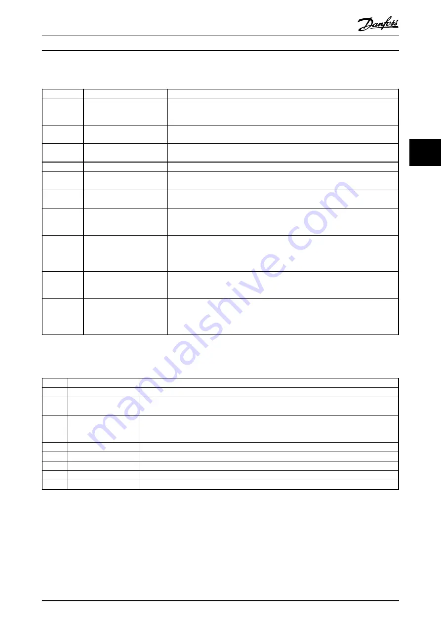
4.5.2 MCO Digital Inputs Terminal (X57)
Terminal
Designation
Description
1
Touch probe switch input
Input triggered on the rising edge. If this signal goes high when no touch probe target
position is locked, a new touch probe target position is calculated and locked in
memory.
2
Positive hardware limit switch
input
Input triggered on the falling edge. Triggers a hardware limit error and the motor is
stopped according to parameter
19-06 Error Behaviour
.
3
Negative hardware limit switch
input
Input triggered on the falling edge. Triggers a hardware limit error and the motor is
stopped according to parameter
19-06 Error Behaviour
.
4
Home reference switch input
Active high. Marks the home position in the application.
5
Go to the target position
Active high. Upon activation the motor goes to the specified target position. A low
signal interrupts any positioning sequence. Not used in fieldbus mode.
6
Reset home flag
Active high. This input clears the home flag. This allows the performance of a 2nd
homing sequence.
7
Reset touch probe position
Active high. This input clears the touch probe position flag. The reset is necessary to
carry out a touch probe positioning command to a new target position. Not used in
fieldbus mode.
8
Quick stop
Active low. This input activates the
Quick Stop
function. The motor is stopped according
to the setting of parameter
19-06 Error Behaviour
. After that, the electromechanical brake
is always activated when the
Quick stop
input is activated, regardless of the parameter
19-06 Error Behaviour
setting.
9
Go to home position
While this input is high the motor executes the homing sequence and no position or
jog operations are carried out. Any homing sequence is interrupted by a low state on
this input. Not used in fieldbus mode.
10
Latch new reference position
index number
Active on the rising edge (must be 0 V for at least 1 ms to guarantee edge detection):
Latches reference position index number specified on terminal 18, 19, 29, 32, 33 into
memory. Digital output 4-8 is changed to mirror the new reference index specified when
using digital input control. Not used in fieldbus mode.
Table 4.3 MCO Digital Inputs Terminal (X57)
4.5.3 MCO Digital Outputs Terminal (X59)
Terminal Designation
Description
1
Homing completed
Active high. This output is always high if an absolute encoder is used.
2
Referenced position
reached
Active high. This output is set when the target position is reached according to the setting of
parameter
33-47 Size of Target Window
.
3
Error occurred
Active high. This output is set every time an error occurs. It is cleared every time a successful error
clear is carried out. This output remains high as long as the power recovery function is selected
(parameter
19-08 Power-Recovery
) and active.
4
Reference index bit 0
Mirror of the currently locked-in reference index bit 0. Not used in fieldbus mode.
5
Reference index bit 1
Mirror of the currently locked-in reference index bit 1. Not used in fieldbus mode.
6
Reference index bit 2
Mirror of the currently locked-in reference index bit 2. Not used in fieldbus mode.
7
Reference index bit 3
Mirror of the currently locked-in reference index bit 3. Not used in fieldbus mode.
8
Reference index bit 4
Mirror of the currently locked-in reference index bit 4. Not used in fieldbus mode.
Table 4.4 MCO Digital Outputs Terminal (X59)
Electrical Installation
Operating Instructions
MG33R302
Danfoss A/S © 04/2014 All rights reserved.
17
4
4
Содержание MCO 351
Страница 2: ......
Страница 57: ...Index Operating Instructions MG33R302 Danfoss A S 04 2014 All rights reserved 55...