DMS Manual
■
Power Wiring
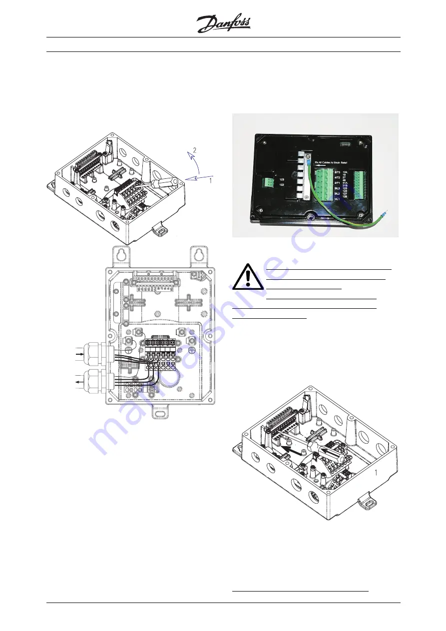
Connect the Supply voltage to the DMS input
terminals 1/L1, 3/L2 & 5/L3.The terminals in the
Extended versions of the DMS allow two cables
to loop the power line as shown.
177ha011.10
Use of screw driver to open the connector clamp
3-phase Mains from
power-bus/
previous unit
3-phase Mains to
next unit
e77ha013.eps
Looping the power line - 3-phase mains
Connect the Motor terminals to the DMS output
terminals 2/T1, 4/T2 & 6/T3. Take care of the phase
sequence to have the correct direction of rotation.
The terminals in the Extended versions of the
DMS allow two cables to connect two motors
in parallel to one DMS.
Maximum cross section: 4 mm sq. (10 AWG)
For ST & SB versions, provide strain relief for power
and control cables by using the cable support
provided in the DMS unit, as shown.
■
Power factor correction
If a DMS is used with static power factor
correction it must be connected to the
supply side of the DMS.
Connecting power factor correction
capacitors to the output of the DMS will result
in damage to the DMS.
■
Control Wiring
Complete the Control wiring as shown in the
Electrical Schematic diagram.
177ha012.10
Use of a screw driver to open the connector clamp
for control terminals [Press to open the clamp]
Rev310103
Connect Control Supply / AS-i Interface at
the terminals provided.
Contacts used for controlling these inputs should be
low voltage, low current rated (Gold flash or similar)
Maximum cross section: 2.5 mm2 (12 AWG)
Use cables complying with local regulations.
MG.05.A2.02 - VLT is a registered Danfoss trademark
6


