


D
GB
F
PT
I
TR
22 | AQ453354265896en-000201
© Danfoss | Climate Solutions | 2023.07
9
|
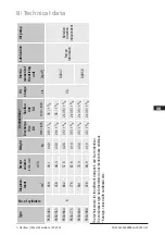
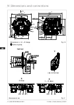
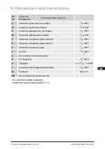
Dimensions and connections
145
305
ca.335
112,5
255
4x 13
135
112,5
ca.370 (375)
X
L
C/E
A
A1
M
G
SV
Zusätzliches SV bei FK(X)50/660-980
Additional SV on FK(X)50/660-980
356
108,4
133,4
190
82
ca.430
ca.
165
ca.115
4xM10x21 LK
210
Y
SV1
D
H
K
F
X
B
B1
DV
Y
Lecköl-Ablass Schlauch
Leak oil drain hose
M
12
x28
2
40
50
54
66
74
100
90
98
110
148
h8
8xM8 130
6xM8 72
A5x9 DIN6888
1:5
1.0851-13918.0 0e
Fahrzeugverdichter / Vehicle Compressor
( ) K Ausführung
( ) K version
Massenschwerpunkt
Centre of gravity
Maße in mm
Dimensions in mm
Änderungen vorbehalten
Subject to change without notice
Typ / type
Teile-Nr. / part-no. Typ / type
Teile-Nr. / part-no. Typ / type
Teile-Nr. / part-no. Typ / type
Teile-Nr. / part-no.
FK(X)50/460 N
13863 (13871) * FK(X)50/460 K
13864 (13872) * FK(X)50/830 N
13916 (13923)
FK(X)50/460 TK
14347 (14351) *
FK(X)50/555 N
13865 (13873) * FK(X)50/555 K
13866 (13874) * FK(X)50/980 N
13918 (13925)
FK(X)50/555 TK
14348 (14352) *
FK(X)50/660 N
13867 (13875)
FK(X)50/660 K
13868 (13876)
FK(X)50/830 K
13917 (13924)
FK(X)50/660 TK
14349 (14353)*
FK(X)50/775 N
13869 (13877)
FK(X)50/775 K
13870 (13878)
FK(X)50/980 K
13919 (13926)
FK(X)50/775 TK
14350 (14354)*
* Keine Serie / No series
Anschlüsse /
Connections
FK(X)50/460+555 FK(X)50/660-980
SV
Saugabsperrventil, Rohr (L)*
mm / Zoll
mm / inch
35 - 1 3/8"
2x35 - 1 3/8"
Suction line valve, tube (L)*
SV1
Opt. Anschlußmöglichkeit Saugabsperrventil
-
-
Opt. connection suction line valve
DV
Druckabsperrventil, Rohr (L)*
mm / Zoll
mm / inch
28 - 1 1/8"
35 - 1 3/8"
Discharge line valve, tube (L)*
A
Anschluß Saugseite, nicht absperrbar
Zoll / inch
1/8“ NPTF
Connection suction side, not lockable
A1
Anschluß Saugseite, absperrbar
Zoll / inch
7/16“ UNF
Connection suction side, lockable
B
Anschluß Druckseite, nicht absperrbar
Zoll / inch
1/8“ NPTF
Connection discharge side, not lockable
B1
Anschluß Druckseite, absperrbar
Zoll / inch
7/16“ UNF
Connection discharge side, lockable
C
Anschluß Öldrucksicherheitsschalter OIL
Zoll / inch
1/8“ NPTF
Connection oil pressure safety switch OIL
D
Anschluß Öldrucksicherheitsschalter LP
Zoll / inch
1/8“ NPTF
Connection oil pressure safety switch LP
E
Anschluß Öldruckmanometer
Zoll / inch
1/8“ NPTF
Connection oil pressure gauge
F
Ölablaß
mm
1/4“ NPTF
Oil drain
G
Opt. Anschlußmöglichkeit Ölsumpfheizung 1)
-
-
Opt. connection oil sump heater 1)
H
Stopfen Ölfüllung
mm
1/4“ NPTF
Oil charge plug
K
Schauglas
Zoll / inch
2 x 1 1/8 “ – 18 UNEF
Sight glass
L
Anschluß Wärmeschutzthermostat
Zoll / inch
1/8“ NPTF
Connection thermal protection thermostat
M
Ölsieb
mm
M22x1,5
Oil filter
(L)* = Lötanschluß
(L)* = Brazing connection
1) = Nur ab Werk möglich
1) = Only possible ex factory
F
E
D
C
A
F
E
D
C
4
1
A
B
5
6
7
8
1
2
3
4
5
6
7
8
Zeichn.-Nr. / Drawing no. :
B
3
2
157148
Dok-ID:
Der Lieferant muss sicherstellen, dass die Ware
in einwandfreiem Zustand angeliefert wird
(Korrosionsschutz, Verpackung für sicheren
Transport).
The supplier has to ensure the delivery of parts
in proper conditions (corrosion prevention,
packaging for safe transportation).
Weitergabe sowie Vervielfältigung dieses Dokuments,
Verwertung und Mitteilung seines Inhalts sind ver-
boten, soweit nicht ausdrücklich gestattet. Zuwider-
handlungen verpflichten zu Schadenersatz. Alle
Rechte für den Fall der Patent-, Gebrauchsmuster-
oder Geschmacksmustereintragung vorbehalten.
The reproduction, distribution and utilization of this
document as well as the communication of its
contents to others without express authorization is
prohibited. Offenders will be held liable for the
payment of damages. All rights reserved in the event
of the grant of a patent, utility
model or design.
Ersatz für / replacement for:
Allgemeintoleranzen / General tolerances
DIN ISO 2768-mK
Ra Rz
22.03.12
Layh
Maß
/
Dimension
Passung / Clearance
h8
147,937
148,000
148
0,000
-0,063
Baumustergeprüft / Type examination:
-
-
K.-Auftrag / C.-Task:
Projektleiter / Project leader:
120
400
±0.5
0.5
6
GEA Bock GmbH - Benzstraße 7 - 72636 Frickenhausen - Germany - www.bock.de
-
-
-
Unbemaßte Radien / Undimensioned radii:
-
Bearb. / Edited
Datum / Date
Änd.-Nr. / Mod-No.
Werkstoff (Zeile 2+3 alternativ) /
Material (Line 2+3 alternative):
Ausgangsteil, Rohteil /
Base part, Raw part:
-
-
Geprüft / Appr.
Name
Datum / Date
22.03.12
22.03.12
Werkstückkanten /
Workpiece edges
DIN ISO 13715
Erstellt / Drawn
Geprüft / Verified
Büttner
Gneiting
1/3
Oberflächenbehandlung, Härte / Treatment of surface, Hardness:
-
Blatt /
Page:
400
Benennung / Description:
±0.8
1000
30
6
-
±0.3
120
30
±0.2
Zeichnungs-Nr. /
Drawing-No.
Oberflächenangaben /
Indication of surface texture
DIN EN ISO 1302
Zust. / Rev.
Gußtoleranzen / General casting tolerances:
Gewicht / Weight: (kg)
±0.1
Maßstab /
Scale:
%
C - FK50/980 N
Rz 25
Rz 160
25
0,05 Rz 1,6
0,3
0,7
1,6
2
Rz 16
6,3 Rz 63
Rz 6,3
Rz 12,5
Status:
-
-
Frei (CAD)
Nein / No
13918 .0
10.08.12
23.05.13
15.01.14
25.03.15
02.12.15
Gneiting
Grass
Gneiting
Egeler_Ch
Grass
0a | Ansicht Sickenrichtung hinzugefügt (Bl.2)
0b | Betrifft Blatt 2
0c | Pos. 570 und Pos. 590 vertauscht (Blatt 3)
0d | Betrifft Blatt 2+3
0e | Betrifft Blatt 3
8351
8527, 8640
8869
9339
9638, 9654
Schaich
Layh
Layh
Layh
Schaich
K - FK50/980 N
-
0851
1.
Kunde / Customer:
-
s
t
u
w
x
y
z
Freigabe / Approved
über / above
bis / up to
Teile-Nr. /
Part-No.
Layh
Shaft end
Leak oil drain hose
Fig. 16
Fig. 17
Dimensions in
() = K + K1 Design
145
305
ca.335
112,5
255
4x 13
135
112,5
ca.370 (375)
X
L
C/E
A
A1
M
G
SV
Zusätzliches SV bei FK(X)50/660-980
Additional SV on FK(X)50/660-980
356
108,4
133,4
190
82
ca.430
ca.
165
ca.115
4xM10x21 LK
210
Y
SV1
D
H
K
F
X
B
B1
DV
Y
Lecköl-Ablass Schlauch
Leak oil drain hose
M
12
x28
2
40
50
54
66
74
100
90
98
110
148
h8
8xM8 130
6xM8 72
A5x9 DIN6888
1:5
1.0851-13918.0 0e
Fahrzeugverdichter / Vehicle Compressor
( ) K Ausführung
( ) K version
Massenschwerpunkt
Centre of gravity
Maße in mm
Dimensions in mm
Änderungen vorbehalten
Subject to change without notice
Typ / type
Teile-Nr. / part-no. Typ / type
Teile-Nr. / part-no. Typ / type
Teile-Nr. / part-no. Typ / type
Teile-Nr. / part-no.
FK(X)50/460 N
13863 (13871) * FK(X)50/460 K
13864 (13872) * FK(X)50/830 N
13916 (13923)
FK(X)50/460 TK
14347 (14351) *
FK(X)50/555 N
13865 (13873) * FK(X)50/555 K
13866 (13874) * FK(X)50/980 N
13918 (13925)
FK(X)50/555 TK
14348 (14352) *
FK(X)50/660 N
13867 (13875)
FK(X)50/660 K
13868 (13876)
FK(X)50/830 K
13917 (13924)
FK(X)50/660 TK
14349 (14353)*
FK(X)50/775 N
13869 (13877)
FK(X)50/775 K
13870 (13878)
FK(X)50/980 K
13919 (13926)
FK(X)50/775 TK
14350 (14354)*
* Keine Serie / No series
Anschlüsse /
Connections
FK(X)50/460+555 FK(X)50/660-980
SV
Saugabsperrventil, Rohr (L)*
mm / Zoll
mm / inch
35 - 1 3/8"
2x35 - 1 3/8"
Suction line valve, tube (L)*
SV1
Opt. Anschlußmöglichkeit Saugabsperrventil
-
-
Opt. connection suction line valve
DV
Druckabsperrventil, Rohr (L)*
mm / Zoll
mm / inch
28 - 1 1/8"
35 - 1 3/8"
Discharge line valve, tube (L)*
A
Anschluß Saugseite, nicht absperrbar
Zoll / inch
1/8“ NPTF
Connection suction side, not lockable
A1
Anschluß Saugseite, absperrbar
Zoll / inch
7/16“ UNF
Connection suction side, lockable
B
Anschluß Druckseite, nicht absperrbar
Zoll / inch
1/8“ NPTF
Connection discharge side, not lockable
B1
Anschluß Druckseite, absperrbar
Zoll / inch
7/16“ UNF
Connection discharge side, lockable
C
Anschluß Öldrucksicherheitsschalter OIL
Zoll / inch
1/8“ NPTF
Connection oil pressure safety switch OIL
D
Anschluß Öldrucksicherheitsschalter LP
Zoll / inch
1/8“ NPTF
Connection oil pressure safety switch LP
E
Anschluß Öldruckmanometer
Zoll / inch
1/8“ NPTF
Connection oil pressure gauge
F
Ölablaß
mm
1/4“ NPTF
Oil drain
G
Opt. Anschlußmöglichkeit Ölsumpfheizung 1)
-
-
Opt. connection oil sump heater 1)
H
Stopfen Ölfüllung
mm
1/4“ NPTF
Oil charge plug
K
Schauglas
Zoll / inch
2 x 1 1/8 “ – 18 UNEF
Sight glass
L
Anschluß Wärmeschutzthermostat
Zoll / inch
1/8“ NPTF
Connection thermal protection thermostat
M
Ölsieb
mm
M22x1,5
Oil filter
(L)* = Lötanschluß
(L)* = Brazing connection
1) = Nur ab Werk möglich
1) = Only possible ex factory
F
E
D
C
A
F
E
D
C
4
1
A
B
5
6
7
8
1
2
3
4
5
6
7
8
Zeichn.-Nr. / Drawing no. :
B
3
2
157148
Dok-ID:
Der Lieferant muss sicherstellen, dass die Ware
in einwandfreiem Zustand angeliefert wird
(Korrosionsschutz, Verpackung für sicheren
Transport).
The supplier has to ensure the delivery of parts
in proper conditions (corrosion prevention,
packaging for safe transportation).
Weitergabe sowie Vervielfältigung dieses Dokuments,
Verwertung und Mitteilung seines Inhalts sind ver-
boten, soweit nicht ausdrücklich gestattet. Zuwider-
handlungen verpflichten zu Schadenersatz. Alle
Rechte für den Fall der Patent-, Gebrauchsmuster-
oder Geschmacksmustereintragung vorbehalten.
The reproduction, distribution and utilization of this
document as well as the communication of its
contents to others without express authorization is
prohibited. Offenders will be held liable for the
payment of damages. All rights reserved in the event
of the grant of a patent, utility
model or design.
Ersatz für / replacement for:
Allgemeintoleranzen / General tolerances
DIN ISO 2768-mK
Ra Rz
22.03.12
Layh
Maß
/
Dimension
Passung / Clearance
h8
147,937
148,000
148
0,000
-0,063
Baumustergeprüft / Type examination:
-
-
K.-Auftrag / C.-Task:
Projektleiter / Project leader:
120
400
±0.5
0.5
6
GEA Bock GmbH - Benzstraße 7 - 72636 Frickenhausen - Germany - www.bock.de
-
-
-
Unbemaßte Radien / Undimensioned radii:
-
Bearb. / Edited
Datum / Date
Änd.-Nr. / Mod-No.
Werkstoff (Zeile 2+3 alternativ) /
Material (Line 2+3 alternative):
Ausgangsteil, Rohteil /
Base part, Raw part:
-
-
Geprüft / Appr.
Name
Datum / Date
22.03.12
22.03.12
Werkstückkanten /
Workpiece edges
DIN ISO 13715
Erstellt / Drawn
Geprüft / Verified
Büttner
Gneiting
1/3
Oberflächenbehandlung, Härte / Treatment of surface, Hardness:
-
Blatt /
Page:
400
Benennung / Description:
±0.8
1000
30
6
-
±0.3
120
30
±0.2
Zeichnungs-Nr. /
Drawing-No.
Oberflächenangaben /
Indication of surface texture
DIN EN ISO 1302
Zust. / Rev.
Gußtoleranzen / General casting tolerances:
Gewicht / Weight: (kg)
±0.1
Maßstab /
Scale:
%
C - FK50/980 N
Rz 25
Rz 160
25
0,05 Rz 1,6
0,3
0,7
1,6
2
Rz 16
6,3 Rz 63
Rz 6,3
Rz 12,5
Status:
-
-
Frei (CAD)
Nein / No
13918 .0
10.08.12
23.05.13
15.01.14
25.03.15
02.12.15
Gneiting
Grass
Gneiting
Egeler_Ch
Grass
0a | Ansicht Sickenrichtung hinzugefügt (Bl.2)
0b | Betrifft Blatt 2
0c | Pos. 570 und Pos. 590 vertauscht (Blatt 3)
0d | Betrifft Blatt 2+3
0e | Betrifft Blatt 3
8351
8527, 8640
8869
9339
9638, 9654
Schaich
Layh
Layh
Layh
Schaich
K - FK50/980 N
-
0851
1.
Kunde / Customer:
-
s
t
u
w
x
y
z
Freigabe / Approved
über / above
bis / up to
Teile-Nr. /
Part-No.
Layh
Centre of gravity
115
165
210
D
F
SV1
4xM10x21
H
K
Y
357
108,5
133,5
405
190
432
+2
304
Y
M
G
L
C/E
A
A1
SV
X
112,5
255
145
4x
13
112,5
331
(334)
+2
372 (380)
+2
130
72
6xM8
A5x9 DIN6888
8xM8
1:5
x
2
8
98
2
110
40
50
54
66
74
100
90
M12
148
h8
lass Schlauch
Leak oil drain hose
DV B
X
Ventilausführung K-Version
valve version K-version
B1
B
DV
B1
X
Ventilausführung N-Version
valve version N-version
( )
( ) K v
N design
K + K1 design
Dimensions in mm


