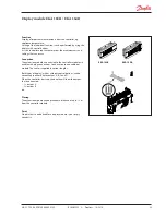

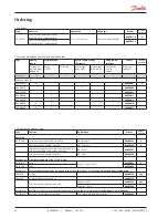


AK-CC 750 - 080Z0130 & 080Z0139
RS8GM222 © Danfoss 10-2014
33
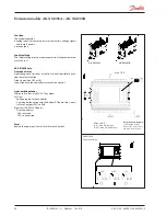
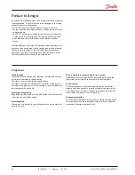
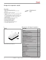
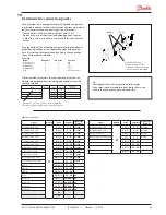
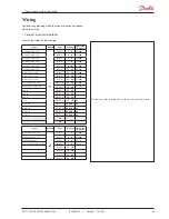
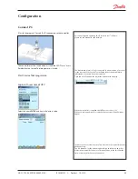
Determine the connection points
All connections must be programmed with module and point, so
in principle it does not matter where the connections are made, as
long as it takes place on a correct type of input or output.
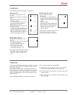
• The controller is the first module, the next one is 2, etc.
• A point is the two or three terminals belonging to an input or
output (e.g. two terminals for a sensor and three terminals for a
relay).
The preparation of the connection diagram and the subsequent
programming (configuration) should take place at the present
time. It is most easily accomplished by filling in the connection
survey for the relevant modules.
Principle:
Name
On module
On Point
Function
fx Compressor 1
x
x
ON
fx Compressor 2
x
x
ON
fx Alarm relay
x
x
OFF
fx Main switch
x
x
Close
fx P0
x
x
AKS 32R 1-6 bar
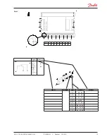
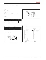
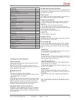
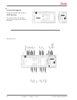
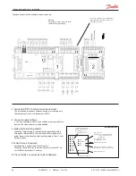
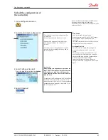
The connection survey from the controller and any extension
modules are uploaded from the paragraph "Module survey. E.g.
controller module:
Module Point
10
Mind the numbering.
The right-hand part of the
controller module may look like
a separate module. But it
isn’t.
- Columns 1, 2, 3 and 5 are used for the programming.
- Columns 2 and 4 are used for the connection diagram.
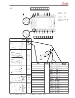
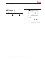
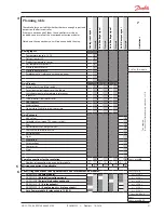
Example continued:
Signal
Module
Point
Terminal
Signal type /
Active at
Air temperature - S3A
1
1
(AI 1)
1 - 2
Pt 1000
Air temperature- S3B
2
(AI 2)
3 - 4
Pt 1000
Air temperature- S3C
3
(AI 3)
5 - 6
Pt 1000
Air temperature - S4A
4
(AI 4)
7 - 8
Pt 1000
Air temperature - S4B
5
(AI 5)
9 - 10
Pt 1000
Air temperature - S4C
6
(AI 6)
11 - 12
Pt 1000
Defrost sensor - S5A
7
(AI 7)
13 - 14
Pt 1000
Defrost sensor - S5B
8
(AI 8)
19 - 20
Pt 1000
Defrost sensor - S5C
9
(AI 9)
21 - 22
Pt 1000
Gas temperature - S2A
10
(AI 10)
23 - 24
Pt 1000
Evaporator pressure - P0
11
(AI 11)
25 - 26
AKS32R-12
AKV A
12
(DO 1)
31 - 32
-
AKV B
13
(DO 2)
33 - 34
-
AKV C
14
(DO 3)
35 - 36
-
Fans
15
(DO 4)
37 - 38
ON
Defrost A
16
(DO 5)
39-40-41
ON
Defrost B
17
(DO6)
42-43-44
ON
Defrost C
18
(DO7)
45-46-47
ON
Rail heat
19
(DO8)
48-49-50
ON
24
-
25
-
Signal
Module
Point
Terminal
Signal type /
Active at
Gas temperature - S2B
2
1
(AI 1)
1 - 2
Pt 1000
Gas temperature - S2C
2
(AI 2)
3 - 4
Pt 1000
External Start/stop
3
(AI 3)
5 - 6
Closed
Case cleaning (pulse pressure)
4
(AI 4)
7 - 8
Closed
5
(AI 5)
17 - 18
6
(AI 6)
19 - 20
7
(AI 7)
21 - 22
8
(AI 8)
23 - 24
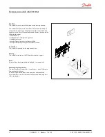
Tip
The Appendix shows 80 general installation types.
If your plant closely resembles one of those shown, you
can use the connection points indicated for it.
Signal
Module
Point
Terminal
Signal type /
Active at
1
(AI 1)
1 - 2
2
(AI 2)
3 - 4
3
(AI 3)
5 - 6
4
(AI 4)
7 - 8


