


30
RS8GM222 © Danfoss 10-2014
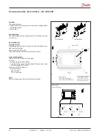
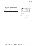
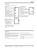
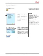
AK-CC 750 - 080Z0130 & 080Z0139
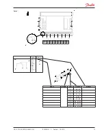
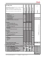
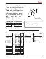
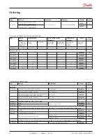
Data from this example is used in the planning table on the
next page.
The result is that the following modules should be used:
• AK-CC 750 controller
• AK-XM 101A
• 3 pcs. EKA 163B
If the result had demonstrated that an additional output was
needed, AK-XM 205A or B would have been the required exten-
sion.
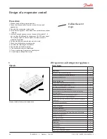
3
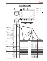
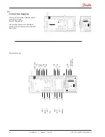
Connections
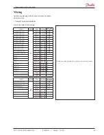
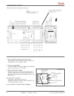
Here is a survey of the possible connections. The texts can be read
in context with the planning table in point 4.
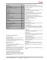
Analog inputs
Temperature sensors each section
• S3 air sensor at evaporator inlet
• S4 air sensor at evaporator outlet (one of the S3/S4 sensors may
be omitted)
.• S5 defrost sensor. Two may be used for long sections
• Product sensor. Extra sensor that only checks the product tem-
perature
• S2 gas sensor at evaporator outlet (control of AKV valve).
Pressure transmitters
• P0 For registration of the evaporating pressure (control of AKV
valve).
• Pc For registration of the condensing pressure. Can be used in
connection with adaptive defrost, or the signal can be received
via data communication.
A pressure transmitter type AKS 32R can supply signals to five
controllers
Voltage signal
Ext. Ref. is used if the thermostat reference is to be displaced
with a signal from another control.
On/Off-inputs
Contact function
(on an analog input) or
voltage signal
(on an
extension module)
• External start/stop of regulation
• Pulse pressure used for the ”appliance cleaning” function
• Switch for changeover between two temperature referenc
• Inject ON. Signal from a compressor control
• Pulse pressure for start of defrost
• Pulse pressure for opening/closing Night blind
• Door switch in coldroom
• External day/night signal (raises the temperature reference when
Night blind is used)
On/off-output
Relay outputs
• Defrost (one each section)
• Rail heat
• Fan motor
• Light
• Compressor (demand on cooling)
• Alarm relay
• Solenoid valve (EVR)
• Drain valve, Suction line valve
• Night blind
• Drip tray heat recovery
AKV Solid state outputs
The solid state outputs on the controller module are primarily
used for AKV valves, but may also be used for the functions men-
tioned under ”relay outputs”.
(The output will always be “OFF” when the controller is hit by
power failure).
Example
• Freezing appliance with three sections
• AKV is used for injections (S2 and P0)
• Electric defrost with stop based on temperature (S5)
• Two thermostat sensors per section (S3 and S4)
• Control of fans and rail heat
• External start/stop (Main switch)
• Switch signal for appliance cleaning
• 3 display for monitoring of appliance temperature


