Kollmorgen
SYSTEM WIRING
SERVO
STAR
®
SP3 Power Block
22
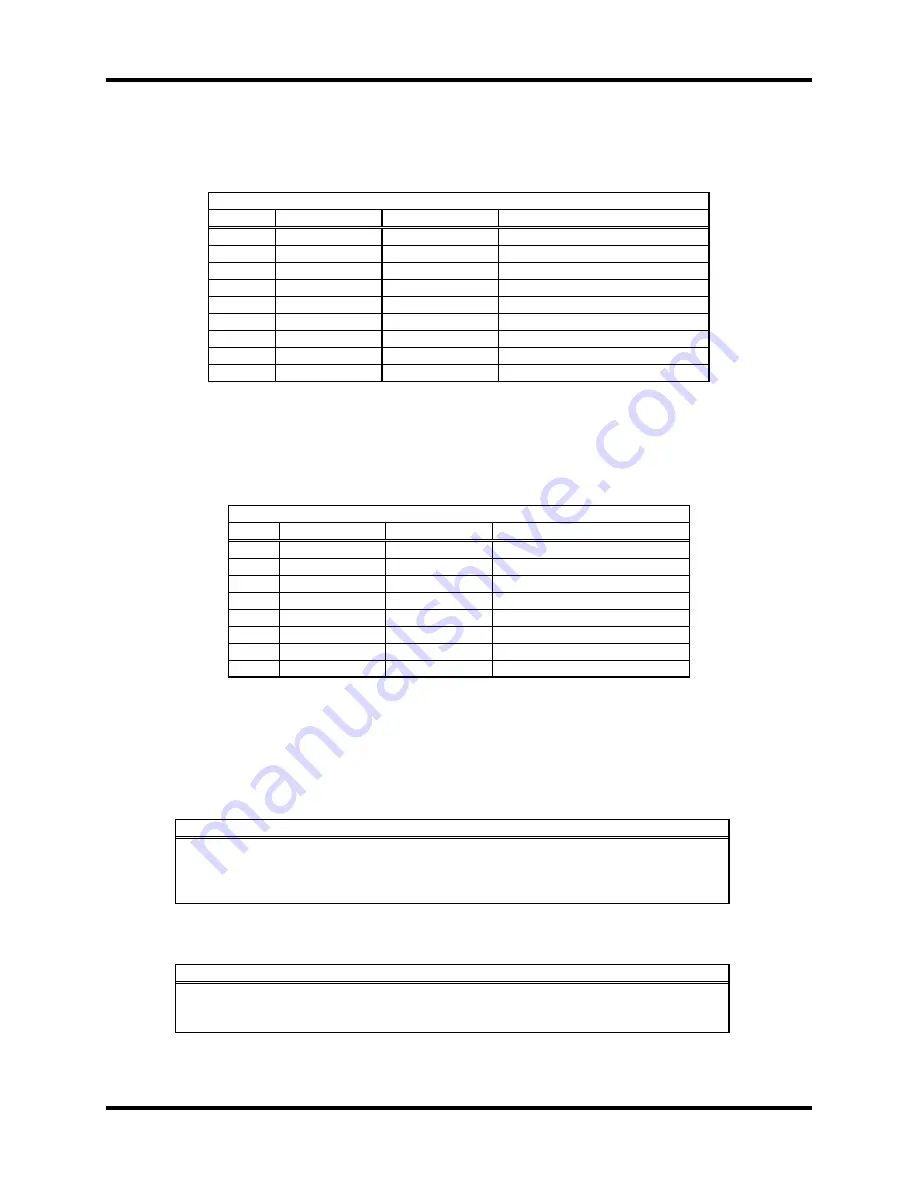
Connector C4: User Flags
Connector C4 returns status information to the user. Connector C4 is a 9 pin D-sub female with
the pin descriptions below.
Connector C4 User Flags
PIN #
SYMBOL
FUNCTION
DESCRIPTION
1 CD_DGND Ground
Analog
Common
2 CD_DGND Ground
Analog
Common
3
FL_RT
Input
Return For All Flags
4
MLIM
Input
Negative Limit Flag
5
USER
Input
General Capture Flag
6 SHIELD
7 Output
Flag
Power
8 HOME
Input
Home
Flag
9
PLIM
Input
Positive Limit Flag
Connector C5 User Flags
On the Integrated 8F Option, connector C5 repeats the user flags that are on connector C4. The
signals on connectors C4 and C5 are interconnected within the drive. Connector C5 is an 8-pin
header, located on the top of the drive, with the pin descriptions below.
Connector C5 User Flags
PIN SYMBOL
FUNCTION DESCRIPTION
1
USER
Input
General Capture Flag
2
PLIM
Input
Positive Limit Flag
3
MLIM
Input
Negative Limit Flag
4 HOME
Input
Home
Flag
5
FL_RT
Input
Return For All Flags
6 CD_DGND Ground
Analog
Common
7
Output
Flag
Power
8 CD_DGND Ground
Analog
Common
DIP SWITCHES
The over-current shut down and the fault code transmission are controlled by four of the ten DIP
switches, which are located on the top of the SP3.
Two DIP switches (S401 numbers 1 and 4) are used for the I
2
T feature. The settings are:
Feature
S401: Switch 1
S401:Switch 4
I
2
T is active
down
down
I
2
T is active
up
down
I
2
T is active
down
up
I
2
T is inactive
up
up
In the PPB, two switches provide a PMAC reading of the Hall effect if the fault detection
function or the fault code are not required. The settings are:
Feature
S401 : Switch 9
S401 :Switch 10
Hall effect reading
up
up
Hall Faults reading
up
down
Faults reading
down
down
www.szcxi.com | From
:
KOLLMORGEN


