background image


- 15 - 

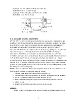
(2). Adjust rear vise to the threaded hole position. (E) 
(3). Set the scale to the desired angle. 
(4). Adjust the front vise (F) to parallel the rear vise(E) 
(5). Tighten the A. B. C. D. Screw. 


8. BLADE GUIDE BEARING ADJUSTMENT 

ATTENTION: This is the most important adjustment on your saw. It is impossible to get 
satisfactory work from your saw if the blade guides are not properly adjusted. The blade 
guide bearings on your metal. Cutting Band Saw are adjusted and power tested with 
several test cuts before leaving the factory to insure proper setting The need for 
adjustment should rarely occur when the saw is used properly. If the guides do get out of 
adjustment though, it is extremely important to readjust immediately. If improper 
adjustment in maintained, the blade will not cut straight, and if the situation is not 
corrected it will cause serious blade damage. Because guide adjustment is a critical factor 
in the performance of your saw, it is always best to try a new blade to see if this will 
correct poor cutting before beginning to adjust. If a blade becomes dull on one side sooner 
than the other, for example, it will begin cutting crooked. A blade change will correct this 
problem the gJide adjustment will not. If a new blade does not correct the problem, check 
the blade guides for proper spacing. 
NOTE: There should be from 000 (just touching) 001 clearance between the blade and 
guide bearings to obtain this clearance adjust as follows: 

1. The inner guide bearing is fixed and cannot be adjusted. 
2. The outer guide bearing is mounted to an eccentric bushing and can be adjusted. 


3. Loosen the nut while holding the bolt with an Alien wrench. 


4. Position the eccentric by turning the bolt to the desired position of clearance. 


5. Tighten the nut.   
6. Adjust the second blade guide bearing in the same manner. 

 
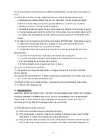
REMARK: 

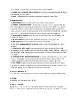
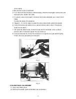
1. Adjust the tension of blade until the back of the blade(A) against the blade wheel 

Содержание SE-712

Страница 1: ...TION MANUAL MODEL SE 712 METAL CUTTING BANDSAW MACHINE 724 Robbins Road Grand Haven MI 49417 Phone 616 842 7110 800 937 3253 Fax 616 842 0859 800 846 3253 Web www dakecorp com E mail customerservice dakecorp com ...

Страница 2: ...pace For Machine Operation 7 7 Make proper tooth selection 7 8 BI Metal speeds and feeds 9 9 Assembly 11 10 Operation 12 11 Blade guide bearing adjustment 15 12 Blade track adjustment 16 13 Maintenance 17 14 Lubrication 18 15 Trouble Shooting 19 20 16 Circuit Diagram 21 23 17 Electrical Specification Chart 22 24 18 Parts Lists 25 31 19 Parts Breakdowns ...

Страница 3: ... 2 ...

Страница 4: ...e end SAFETY RULES FOR ALL TOOLS A USER 1 WEAR PROPER APPAREL No loose clothing gloves rings bracelets or other jewelry to get caught in moving parts Non slip foot wear is recommended Wear protective hair covering to contain long hair 2 ALWAYS WEAR EYE PROTECTION Refer to ANSLZ87 1 standard for appropriate recommendations Also use face or dust mask if cutting operation is dusty 3 DON T OVERREACH K...

Страница 5: ...work into a blade or cutter against the direction of rotation of the blade or cutter only 9 ADJUST AND POSITION the blade guide arm before starting the cut 10 KEEP BLADE GUIDE ARM TIGHT A loose blade guide arm will affect sawing accuracy 11 MAKE SURE blade speed is set correctly for material being cut 12 CHECK for proper blade size and type 13 STOP the machine before putting material in the vise 1...

Страница 6: ...ade 6 TO RPOLONG BLADE LIFE ALWAYS release blade tension at the end of each work day 7 CHECK COOLANT DAILY Low coolant level can cause foaming and high blade temperatures Dirty or week coolant can clog pump cause crooked Cast low cutting rate and permanent blade failure Dirty coolant can cause the growth of bacteria with ensuing skin irritation 8 WHEN CUTTING MAGNESIUM NEVER use soluble oils or em...

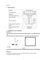
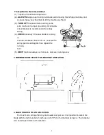
Страница 7: ...LxWxH 1270 x 470 x 965 mm Overall height w o stand 1092mm 43 Noise 80 dB MAX 2 TRANSPORTATION OF MACHINE Unpacking 1 Transportation to desired location before unpacking please use lifting jack Fig B 2 Transportation after unpacking please use heavy duty fiber belt to lift up the machine Fig B ALLWAYS KEEP PROPER FOOTING BALANCE WHILE MOVING THIS MACHINE Installation As this machine weights 125 kg ...

Страница 8: ...d for safety wiring 4 CHECK carefully if the saw blade is running in counter clockwise direction if not reverse the wiring per circuit diagram then repeat the running test 5 KEEP machine always out from sun dust wet raining area 3 MINIMUM ROOM SPACE FOR MACHINE OPERATION 4 MAKE PROPER TOOTH SELECTION For maximum cutting efficiency and lowest cost per cut it is important to select the blade with th...

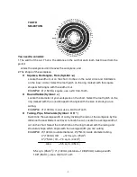
Страница 9: ...orkpiece on the chart Select the tooth pitch on the ring marked with the round shape which aligns with the size of stock you are cutting EXAMPLE 4 100mm round use a 3 4 Vari Tooth Tubing Pipe Structurals Symbol O H Determine the average width of cut by dividing the area of the workpiece by the distance the saw blade must travel to finish the cut Locate the average width of cut on the chart Select ...

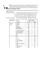
Страница 10: ... 4 32 mm material 5 8 Vari Tooth 5 When cutting 2 1 2 64 mm material 4 6 Vari Tooth Decrease Band Speed 12 When cutting 8 200mm material 2 3 Vari Tooth BAND SPEED MATERIAL ALLOY ASTM NO FT MIN M MIN 173 932 314 96 330 365 284 87 623 624 264 81 230 260 272 244 74 280 264 632 655 244 74 101 102 110 122 172 234 71 1751 182 220 510 234 71 625 706 715 934 234 71 630 229 70 Copper Alloy 811 214 65 1117 ...

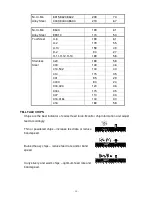
Страница 11: ...502 140 43 414 115 35 431 95 29 440C 80 24 304 324 120 36 304L 115 35 347 110 33 316 316L 100 30 Stainless Steel 416 189 58 TELLTALE CHIPS Chips are the best indicator of correct feed force Monitor chip information and adjust feed accordingly Thin or powdered chips increase feed rate or reduce band speed Burned heavy chips reduce feed rate and or band speed Curly silvery and warm chips optimum fee...

Страница 12: ...e Shaft 5 Assemble the Motor Pulley the smaller of the two provided to the motor shaft Note the larger diameter must be closest to the motor Do not tighten the set screw 6 Assemble the Driven Pulley the larger of the two provided to the protruding drive Shaft Note the small diameter must be closest to the bearing Do not tighten the set screw 7 Place the belt into one of the pulley grooves and the ...

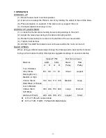
Страница 13: ...Tighten thumbscrew 5 DO NOT ALLOW the blade to rest on the work while the motor is shut off BLADE SPEEDS When using your Band saw always change the blade speed to best suit the material being cut the material Cutting Shart givers suggested settings for several materials Speed F P M Belt Groove Used 60Hz 50Hz Material A B A B Motor Pulley Saw Pulley Tool Stainless Alloy Steels Bearing Bronze 85 98 ...

Страница 14: ...aw to come to full speed then begin the cut by letting the head down slowly onto the work DO NOT DROP OR FORCE Let the weight of the saw head provide the cutting force The saw automatically shuts off at the end of the cut BLADE SELECTION A 8 tooth per inch general use blade is furnished with this metal Cutting Band Saw Additional blades in 4 6 8 and 10 tooth sizes are available The choice of blade...

Страница 15: ... Made to continue the application on the upward pull on the blade 5 Remove right hand from blade and adjust the position of the top pulley to permit left hand to slip the blade around the pulley using the thumb index and little finger as guides 6 Adjust the blade tension knob clockwise until it is just right enough so no blade slippage occurs Do not tighten excessively 7 Replace the blade guards 8...

Страница 16: ...e damage Because guide adjustment is a critical factor in the performance of your saw it is always best to try a new blade to see if this will correct poor cutting before beginning to adjust If a blade becomes dull on one side sooner than the other for example it will begin cutting crooked A blade change will correct this problem the gJide adjustment will not If a new blade does not correct the pr...

Страница 17: ...ps to adjust the other side s blade guide bearings G 6 Correct the base and blade to be a vertical position with a scale If necessary loosen set screw F 7 Set down the blade frame correct the jaw vise H and blade to be a vertical position with a scale then tighten the set screws I 8 Loosen set screw K move front jaw vise J to against rear jaw vise H tightly Finish correcting by tighting set screw ...

Страница 18: ... the set screw clockwise until it bottoms then continue for half a turn and check the tracking by turning on the machine d If further adjustment is required go back to step 4 6 Turn off power to the machine 7 Replace the clade guide assemblies it may be necessary to loosen the blade tension alightly 8 Adjust the vertical position of blade guide bearing assemblies so that the back side of the blade...

Страница 19: ...oid loosening or wearing LUBRICATION Lubricate the following components using SAE 30 oil as noted 1 Ball bearing none 2 Driven pulley bearing 6 8 drops a week 3 Vise lead screw as needed 4 The drive gears run in an oil bath and will not require a lubricant change more often than once a year unless the lubricant is accidentally contaminated or a leak occurs because of improper replacement of the ge...

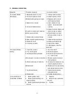
Страница 20: ...work after motor is starred 7 Adjust wheel alignment 8 Adjust guide bearings 9 Use thinner blade 10 Weld again note the weld skill Premature Blade Dulling 1 Teeth too coarse 2 Too much speed 3 Inadequate feed pressure 4 Hard spots or scale on material 5 Work hardening of material 6 Blade twist 7 Insufficient blade 8 Blade slide 1 Use finer teeth 2 Decrease speed 3 Decrease spring tension on side o...

Страница 21: ...h 7 Decrease reed anti speed Bad Cuts Crooked 1 Feed pressure too great 2 Guide bearings not adjusted properly 3 Inadequate blade tension 4 Dull blade 5 Speed incorrect 6 Blade guides spaced out too much 7 Blade guide assembly loose 8 Blade truck too far away from wheel flanges 1 Reduce pressure by increasing spring tension on side of saw 2 Adjust guide bearing the clearance can not greater than 0...

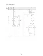
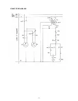
Страница 22: ... 21 CIRCUIT DIAGRAM ...

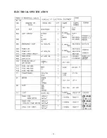
Страница 23: ... 22 ELECTRICAL SPECIFICATION ...

Страница 24: ... 23 CIRCUIT DIAGRAM ...

Страница 25: ... 24 ELECTRICAL SPECIFICATION ...

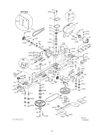
Страница 26: ... 25 ...

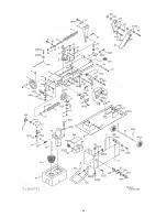
Страница 27: ... 26 ...

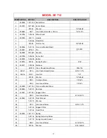
Страница 28: ...ng Washer 3 16 15 300911 191206 Retainer 16 HS519 Cross Round Head Screw M5x10L 17 43331 S410 Hex Socket Head Screw 3 8 x1 1 2 L 18 43916 N001 Hex Nut 1 2 19 W002 Washer 1 2 x28xt2 20 S501 Carriage Screw 1 2 x2 L 21 S003 Hex Head Screw 1 2 x2 L 22 300939 181113 1 Vise Jaw Bracket Rear 23 300940 181121 Bushing 24 300941 181122 1 Support Rod 25 S022 Hex Head Screw 5 16 x3 4 L 26 300942 181123 Pivot ...

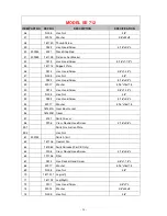
Страница 29: ...S014 Hex Head Screw 3 8 x1 3 4 L 51 N005 Hex Nut 3 8 52 S022 Hex Head Screw 5 16 x3 4 L 53 W017 Washer 5 16 x18xt1 5 55 181431A Gear Box Gasket 56 181420B Cover 57 3131 Switch Cover 58 S708 Cross Round Head Screw 3 16 x3 8 L 59 1 Switch Instruction Plate 59 2 Hex Nut 61 300733 Switch limit 62 181106 Coolant Pan 63 181989 Switch Bracket For CE Only 64 S708 Cross Round Head Screw 3 16 x3 8 L 65 1911...

Страница 30: ...181304 2 Cylinder Complete Set RF 712N 99 W017 Washer 5 16 x18xt1 5 100 S017 Hex Head Screw 5 16 x1 L 101 S412 Hex Socket Head Screw 3 8 x2 1 4 L Threaded 102 W013 Washer 3 8 x20xt2 113 300952 181242B Brush Support 114 W007 Washer 3 16 x12xt0 8 115 S708 Cross Round Head Screw 3 16 x3 8 L 116 192029 Bearing Spacer 117 181307 Bushing 118 HS422 Hex Socker Headless Screw M6x10L 119 K003 Key 5x5x15L 12...

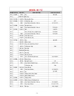
Страница 31: ...ey 6x6x20L 217 181220 1 Worm Gear 218 181219 1 Transmission Wheel Shaft 219 HCS13 C Retainer Ring S25 221 181218 1 Bushing 222 CA6205LU Bearing 223 181217 1 Bushing 225 181246 Bearing Cover 226 S712 Cross Round Head Screw 5 32 x3 8 L 227 300946 181203 1 Body Frame 228 W204 Spring Washer 3 8 229 S013 Hex Socket Head Screw 3 8 x1 1 4 L 230 C Retainer ring S26 231 300947 181214 2 Drive Wheel 232 S022...

Страница 32: ...01272 3066 3 Blade Adjustable Knob 262 300949 181228 1 Adjustable Bracket Rear 263 N006 Hex Nut 3 8 UNF 264 W208 Spring Washer 3 8 265 10026 01 CA6000ZZ Bearing 266 300950 3064 Blade Adjustable Rear Hole 267 301446 3063 Bearing Pin 268 W017 Washer 5 16 x18xt1 5 269 W205 Spring Washer 5 16 270 S416 Hex Socket Head Screw 5 16 x1 1 4 L 271 3069 Deflector Plate 272 S301 Flat Cross Head Screw 1 4 x1 2 ...

Страница 33: ...19xt1 5 295 300957 K008 Key 5x5x30L 296 S604 Hex Socker Headless Screw 1 4 x3 8 L 297 300959 181235 Motor Pulley 298 S503 Screw 5 16 x1 L 299 S013 Hex Socket Head Screw 3 8 x1 1 4 L 300 300741 M301 Motor 3 4HP 110 60 1PH 301 S021 Hex Head Screw 5 16 x2 L 302 N007 Hex Nut 5 16 303 181234A Motor Mount Plate 304 N007 Hex Nut 5 16 305 S022 Hex Head Screw 5 16 x3 4 L 306 W016 Washer 5 16 x23xt2 307 181...

Страница 34: ...tor For CE Only 345 181991 Emergency Switch Bracket For CE Only 348 S727 Cross Round Head Screw M6x12L 349 S726 Cross Round Head Screw M6x10L 352 W016 Washer 5 16 x19xt1 5 353 S018 Hex Head Screw 5 16 x1 2 L 355 N005 Hex Nut 3 8 356 181979 Hose Bib 357 W018 Washer 5 16 x23xt3 358 S022 Hex Head Screw 5 16 x3 4 L 371 ET1304 Wire Nipple 1 2 375 S708 Cross Round Head Screw 3 16 x3 8 L 388 Limit Switch...

Отзывы: