


Si39-502A
Specifications
Specifications
27
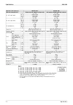
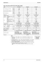
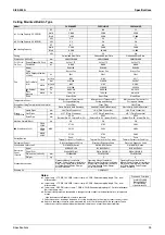
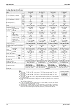
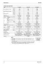
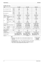
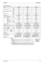
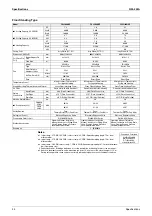
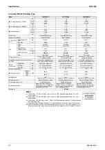
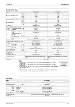
Ceiling Mounted Built-in Type
Notes:
1 Indoor temp. : 27°CDB, 19.5°CWB / outdoor temp.: 35°CDB / Equivalent piping length: 7.5m, level
difference: 0m.
2 Indoor temp. : 27°CDB, 19.0°CWB / outdoor temp.: 35°CDB / Equivalent piping length: 7.5m, level
difference: 0m.
3 Indoor temp. : 20°CDB / outdoor temp.: 7°CDB, 6°CWB / Equivalent piping length: 7.5m, level difference:
0m. (Heat pump only)
4 External static pressure is changeable to change over the connectors inside electrical box, this pressure
means
“High static pressure-Standard”.
5 Capacities are net, including a deduction for cooling (an additional for heating) for indoor fan motor heat.
6 Anechoic chamber conversion value, measured at a point 1.5m downward from the unit center. These
values are normally somewhat higher during actual operation as a result of ambient conditions.
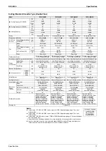
Model
FXSQ80MVE
FXSQ100MVE
FXSQ125MVE
1 Cooling Capacity (19.5°CWB)
RT
2.6
3.3
4.1
kcal/h
8,000
10,000
12,500
Btu/h
31,700
39,600
49,500
kW
9.3
11.6
14.5
2 Cooling Capacity (19.0°CWB)
kW
9.0
11.2
14.0
3 Heating Capacity
RT
2.8
3.6
4.5
kcal/h
8,600
10,800
13,800
Btu/h
34,100
42,700
54,600
kW
10.0
12.5
16.0
Casing
Galvanized Steel Plate
Galvanized Steel Plate
Galvanized Steel Plate
Dimensions: (H×W×D)
mm
300×1,400×800
300×1,400×800
300×1,400×800
Coil (Cross
Fin Coil)
Rows×Stages×Fin Pitch
mm
3×14×1.75
3×14×1.75
3×14×1.75
Face Area
m²
0.338
0.338
0.338
Fan
Model
3D18H2A
3D18H2A
3D18H2A
Type
Sirocco Fan
Sirocco Fan
Sirocco Fan
Motor Output × Number of
Units
W
225×1
225×1
225×1
Air Flow Rate
(H/L)
50Hz
m³/min
27/21.5
28/22
38/28
cfm
953/759
988/777
1341/988
60Hz
m³/min
27/20.5
28/21
38/27
cfm
953/724
988/741
1341/953
4 External
static pressure
50Hz
Pa
113-82
107-75
78-39
60Hz
Pa
147-92
136-83
78-20
Drive
Direct Drive
Direct Drive
Direct Drive
Temperature Control
Microprocessor Thermostat for
Cooling and Heating
Microprocessor Thermostat for
Cooling and Heating
Microprocessor Thermostat for
Cooling and Heating
Sound Absorbing Thermal Insulation Material
Glass Fiber
Glass Fiber
Glass Fiber
Air Filter
Resin Net (with Mold Resistant)
Resin Net (with Mold Resistant)
Resin Net (with Mold Resistant)
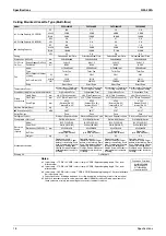
Piping
Connections
Liquid Pipes
mm
φ
9.5 (Flare Connection)
φ
9.5 (Flare Connection)
φ
9.5 (Flare Connection)
Gas Pipes
mm
φ
15.9 (Flare Connection)
φ
15.9 (Flare Connection)
φ
15.9 (Flare Connection)
Drain Pipe
mm
VP25
(External Dia. 32 Internal Dia. 25)
VP25
(External Dia. 32 Internal Dia. 25)
VP25
(External Dia. 32 Internal Dia. 25)
Machine Weight (Mass)
kg
51
51
52
6 Sound Level (H/L)
50Hz
220V
dBA
43/37
43/37
46/41
50Hz
240V
45/39
45/39
48/43
60Hz
220V
43/37
43/37
46/41
Safety Devices
Fuse,
Thermal Protector for Fan Motor
Fuse,
Thermal Protector for Fan Motor
Fuse,
Thermal Protector for Fan Motor
Refrigerant Control
Electronic Expansion Valve
Electronic Expansion Valve
Electronic Expansion Valve
Connectable outdoor unit
R-410A M(A) Series
R-410A M(A) Series
R-410A M(A) Series
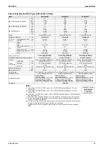
Decoration
Panel
(Option)
Model
BYBS125DJW1
BYBS125DJW1
BYBS125DJW1
Panel Color
White (10Y9/0.5)
White (10Y9/0.5)
White (10Y9/0.5)
Dimensions: (H×W×D)
mm
55×1,500×500
55×1,500×500
55×1,500×500
Weight
kg
6.5
6.5
6.5
Standard Accessories
Operation Manual, Installation
Manual, Paper Pattern for Installation,
Drain Hose, Clamp Metal, Insulation
for Fitting, Sealing Pads, Clamps,
Screws, Washers.
Operation Manual, Installation
Manual, Paper Pattern for Installation,
Drain Hose, Clamp Metal, Insulation
for Fitting, Sealing Pads, Clamps,
Screws, Washers.
Operation Manual, Installation
Manual, Paper Pattern for Installation,
Drain Hose, Clamp Metal, Insulation
for Fitting, Sealing Pads, Clamps,
Screws, Washers.
Drawing No.
C: 3D039431
Conversion Formulae
kcal/h=kW×860
Btu/h=kW×3412
RT=kW×0.284
cfm=m³/min×35.3
Содержание VRV II RXYQ8MY1K
Страница 18: ...Si39 502A Specifications 7 Part 2 Specifications 1 Specifications 8 1 1 Outdoor Units 8 1 2 Indoor Units 16...
Страница 53: ...Specifications Si39 502A 42 Specifications...
Страница 143: ...Field Setting Si39 502A 132 Test Operation...
Страница 247: ...Piping Diagrams Si39 502A 236 Appendix 1 Piping Diagrams 1 1 Outdoor Unit RXYQ8MY1K E YLK E RXYQ10MY1K E YLK E 3D049524...
Страница 250: ...Si39 502A Piping Diagrams Appendix 239 FXUQ BEVQ Indoor unit Connection Unit 4D037995F 4D034127B...
Страница 251: ...Piping Diagrams Si39 502A 240 Appendix FXAQ BEVQ Indoor unit Connection Unit 4D047084 4D034127B...
Страница 252: ...Si39 502A Piping Diagrams Appendix 241 FXLQ BEVQ Indoor unit Connection Unit 4D047084 4D034127B...
Страница 254: ...Si39 502A Wiring Diagrams for Reference Appendix 243 2 2 Field Wiring RXYQ8MY1K E YLK E RXYQ10MY1K E YLK E 3D040746J...
Страница 255: ...Wiring Diagrams for Reference Si39 502A 244 Appendix RXYQ16MY1K E YLK E RXYQ18MY1K E YLK E RXYQ20MY1K E YLK E 3D040747H...
Страница 257: ...Wiring Diagrams for Reference Si39 502A 246 Appendix 2 3 Indoor Unit FXCQ20M 25M 32M 63MVE 3D039556A...
Страница 258: ...Si39 502A Wiring Diagrams for Reference Appendix 247 FXCQ40M 50M 80M 125MVE 3D039557A...
Страница 259: ...Wiring Diagrams for Reference Si39 502A 248 Appendix FXFQ25M 32M 40M 50M 63M 80M 100M 125MVE 3D039600A...
Страница 260: ...Si39 502A Wiring Diagrams for Reference Appendix 249 FXKQ25M 32M 40M 63MVE 3D039564A...
Страница 261: ...Wiring Diagrams for Reference Si39 502A 250 Appendix FXDQ20N 25N 32N 40N 50N 63NVE with Drain Pump 3D045500B...
Страница 262: ...Si39 502A Wiring Diagrams for Reference Appendix 251 FXDQ20N 25N 32N 40N 50N 63NVET without Drain Pump 3D049604A...
Страница 263: ...Wiring Diagrams for Reference Si39 502A 252 Appendix FXSQ20M 25M 32M 40M 50M 63M 80M 100M 125MVE 3D039561A...
Страница 264: ...Si39 502A Wiring Diagrams for Reference Appendix 253 FXMQ40M 50M 63M 80M 100M 125MVE 3D039620A...
Страница 265: ...Wiring Diagrams for Reference Si39 502A 254 Appendix FXMQ200M 250MVE 3D039621A...
Страница 266: ...Si39 502A Wiring Diagrams for Reference Appendix 255 FXHQ32M 63M 100MVE 3D039801C...
Страница 267: ...Wiring Diagrams for Reference Si39 502A 256 Appendix FXAQ20M 25M 32M 40M 50M 63MVE 3D034206A...
Страница 269: ...Wiring Diagrams for Reference Si39 502A 258 Appendix FXUQ71M 100M 125MV1 3D044973...
Страница 270: ...Si39 502A Wiring Diagrams for Reference Appendix 259 FXAQ20MH 25MH 32MH 40MH 50MHV1 3D046348A...
Страница 271: ...Wiring Diagrams for Reference Si39 502A 260 Appendix FXLQ20MH 25MH 32MH 40MH 50MHV1 3D046787A...
Страница 272: ...Si39 502A Wiring Diagrams for Reference Appendix 261 BEVQ50MVE 3D046579A Notes...
Страница 273: ...Wiring Diagrams for Reference Si39 502A 262 Appendix BEVQ71M 100M 125MVE 3D044901A Notes...
Страница 285: ...Piping Installation Point Si39 502A 274 Appendix...
Страница 293: ...Method of Replacing The Inverter s Power Transistors and Diode Modules Si39 502A 282 Appendix...
Страница 307: ...Si39 502A iv Index...


