


Si39-502A
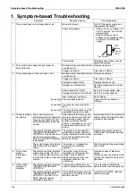
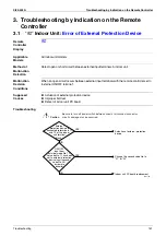
Symptom-based Troubleshooting
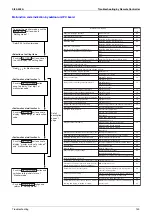
Troubleshooting
137
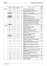
Symptom
Supposed Cause
Countermeasure
7
The system
conducts air
blasting
operation but not
cooling or
heating
operation.
This symptom occurs
immediately after turning ON
the power supply.
The system is in preparation
mode of operation.
Wait for a period of approximately
10 minutes.
8
The airflow rate
is not
reproduced
according to the
setting.
Even pressing the AIRFLOW
RATE SET button makes no
changes in the airflow rate.
In heating operation, when the
room temperature reaches the set
degree, the outdoor unit will stop
while the indoor unit is brought to
breezing operation so that no one
gets cold air.
Furthermore, if blasting mode is
selected when other indoor unit is
in heating operation, the system
will be brought to breezing
operation.
(The breezing operation is also
enabled while in oil return mode in
cooling operation.)
Normal operation.
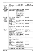
9
The airflow
direction is not
reproduced
according to the
setting.
The airflow direction is not
corresponding to that
displayed on the remote
controller.
The flap does not swing.
Automatic control
Normal operation.
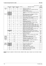
10 A white mist
comes out from
the system.
<Indoor unit>
In cooling operation, the
ambient humidity is high.
(This indoor unit is installed in
a place with much oil or dust.)
Uneven temperature distribution
due to heavy stain of the inside of
the indoor unit
Clean the inside of the indoor unit.
<Indoor unit>
Immediately after cooling
operation, the ambient
temperature and humidity are
low.
Hot gas (refrigerant) flown in the
indoor unit results in humidity.
Normal operation.
<Indoor and outdoor units>
After the completion of
defrosting operation, the
system is switched to heating
operation.
Defrosted moisture turns to be
vapor and comes out from the
units.
Normal operation.
11 The system
produces
sounds.
<Indoor unit>
Immediately after turning ON
the power supply, indoor unit
produces "ringing" sounds.
These are operating sounds of
the electronic expansion valve of
the indoor unit.
Normal operation.
This sound becomes low after a
lapse of approximately one
minute.
<Indoor and outdoor units>
"Hissing" sounds are
continuously produced while in
cooling or defrosting operation.
These sounds are produced from
gas (refrigerant) flowing
respectively through the indoor
and outdoor units.
Normal operation.
<Indoor and outdoor units>
"Hissing" sounds are produced
immediately after the startup or
stop of the system, or the
startup or stop of defrosting
operation.
These sounds are produced
when the gas (refrigerant) stops
or changes flowing.
Normal operation.
<Indoor unit>
Faint sounds are continuously
produced while in cooling
operation or after stopping the
operation.
These sounds are produced from
the drain discharge device in
operation.
Normal operation.
<Indoor unit>
"Creaking" sounds are
produced while in heating
operation or after stopping the
operation.
These sounds are produced from
resin parts expanding and
contracting with temperature
changes.
Normal operation.
<Indoor unit>
Sounds like "trickling" or the
like are produced from indoor
units in the stopped state.
On multi-unit systems, these
sounds are produced from other
indoor units in operation. The
reason is that the system runs in
order to prevent oil or refrigerant
from dwelling.
Normal operation.
<Outdoor unit>
Pitch of operating sounds
changes.
The reason is that the compressor
changes the operating frequency.
Normal operation.
Содержание VRV II RXYQ8MY1K
Страница 18: ...Si39 502A Specifications 7 Part 2 Specifications 1 Specifications 8 1 1 Outdoor Units 8 1 2 Indoor Units 16...
Страница 53: ...Specifications Si39 502A 42 Specifications...
Страница 143: ...Field Setting Si39 502A 132 Test Operation...
Страница 247: ...Piping Diagrams Si39 502A 236 Appendix 1 Piping Diagrams 1 1 Outdoor Unit RXYQ8MY1K E YLK E RXYQ10MY1K E YLK E 3D049524...
Страница 250: ...Si39 502A Piping Diagrams Appendix 239 FXUQ BEVQ Indoor unit Connection Unit 4D037995F 4D034127B...
Страница 251: ...Piping Diagrams Si39 502A 240 Appendix FXAQ BEVQ Indoor unit Connection Unit 4D047084 4D034127B...
Страница 252: ...Si39 502A Piping Diagrams Appendix 241 FXLQ BEVQ Indoor unit Connection Unit 4D047084 4D034127B...
Страница 254: ...Si39 502A Wiring Diagrams for Reference Appendix 243 2 2 Field Wiring RXYQ8MY1K E YLK E RXYQ10MY1K E YLK E 3D040746J...
Страница 255: ...Wiring Diagrams for Reference Si39 502A 244 Appendix RXYQ16MY1K E YLK E RXYQ18MY1K E YLK E RXYQ20MY1K E YLK E 3D040747H...
Страница 257: ...Wiring Diagrams for Reference Si39 502A 246 Appendix 2 3 Indoor Unit FXCQ20M 25M 32M 63MVE 3D039556A...
Страница 258: ...Si39 502A Wiring Diagrams for Reference Appendix 247 FXCQ40M 50M 80M 125MVE 3D039557A...
Страница 259: ...Wiring Diagrams for Reference Si39 502A 248 Appendix FXFQ25M 32M 40M 50M 63M 80M 100M 125MVE 3D039600A...
Страница 260: ...Si39 502A Wiring Diagrams for Reference Appendix 249 FXKQ25M 32M 40M 63MVE 3D039564A...
Страница 261: ...Wiring Diagrams for Reference Si39 502A 250 Appendix FXDQ20N 25N 32N 40N 50N 63NVE with Drain Pump 3D045500B...
Страница 262: ...Si39 502A Wiring Diagrams for Reference Appendix 251 FXDQ20N 25N 32N 40N 50N 63NVET without Drain Pump 3D049604A...
Страница 263: ...Wiring Diagrams for Reference Si39 502A 252 Appendix FXSQ20M 25M 32M 40M 50M 63M 80M 100M 125MVE 3D039561A...
Страница 264: ...Si39 502A Wiring Diagrams for Reference Appendix 253 FXMQ40M 50M 63M 80M 100M 125MVE 3D039620A...
Страница 265: ...Wiring Diagrams for Reference Si39 502A 254 Appendix FXMQ200M 250MVE 3D039621A...
Страница 266: ...Si39 502A Wiring Diagrams for Reference Appendix 255 FXHQ32M 63M 100MVE 3D039801C...
Страница 267: ...Wiring Diagrams for Reference Si39 502A 256 Appendix FXAQ20M 25M 32M 40M 50M 63MVE 3D034206A...
Страница 269: ...Wiring Diagrams for Reference Si39 502A 258 Appendix FXUQ71M 100M 125MV1 3D044973...
Страница 270: ...Si39 502A Wiring Diagrams for Reference Appendix 259 FXAQ20MH 25MH 32MH 40MH 50MHV1 3D046348A...
Страница 271: ...Wiring Diagrams for Reference Si39 502A 260 Appendix FXLQ20MH 25MH 32MH 40MH 50MHV1 3D046787A...
Страница 272: ...Si39 502A Wiring Diagrams for Reference Appendix 261 BEVQ50MVE 3D046579A Notes...
Страница 273: ...Wiring Diagrams for Reference Si39 502A 262 Appendix BEVQ71M 100M 125MVE 3D044901A Notes...
Страница 285: ...Piping Installation Point Si39 502A 274 Appendix...
Страница 293: ...Method of Replacing The Inverter s Power Transistors and Diode Modules Si39 502A 282 Appendix...
Страница 307: ...Si39 502A iv Index...