


Field Setting
Si39-502A
102
Test Operation
3.1.7
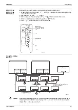
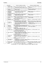
Centralized Control Group No. Setting
BRC1A Type
Set the group number of each group of the indoor unit from the remote controller. (In case of no
remote controller, also connect the remote controller and set the group No. Then, remove the
remote controller.)
1. Turn ON the power of the indoor unit and central remote controller.
(Unless the power is ON, no setting can be made.)
Check that the installation and electrical wiring are correct before turning the power supply
ON.
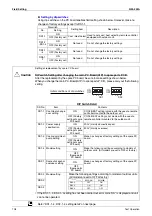
(When the power supply is turned ON, all LCD appear once and the unit may not accept the
operation for about one minute with the display of “
88
”.)
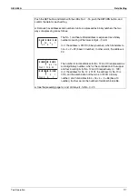
2. While in the normal mode, hold down the “
” button for a minimum of 4 seconds.
The remote controller will enter the FIELD SET MODE.
3. Select the MODE No. “
00
” with the “
” button.
4. Use the “
” button to select the group No. for each group.
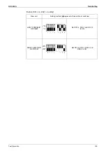
5. (Group numbers increase in the order of 1-00, 1-01, ... 1-15, 2-00, ... 4-15.)
6. Press “
” to set the selected group No.
7. Press “
” to return to the NORMAL MODE.
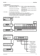
Note:
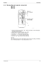
For wireless remote controller, see the following.
For setting group No. of HRV and wiring adaptor for other air conditioners, etc., refer to the
instruction manual attached.
NOTICE
Enter the group No. and installation place of the indoor unit into the attached installation table.
Be sure to keep the installation table with the operation manual for maintenance.
Содержание VRV II RXYQ8MY1K
Страница 18: ...Si39 502A Specifications 7 Part 2 Specifications 1 Specifications 8 1 1 Outdoor Units 8 1 2 Indoor Units 16...
Страница 53: ...Specifications Si39 502A 42 Specifications...
Страница 143: ...Field Setting Si39 502A 132 Test Operation...
Страница 247: ...Piping Diagrams Si39 502A 236 Appendix 1 Piping Diagrams 1 1 Outdoor Unit RXYQ8MY1K E YLK E RXYQ10MY1K E YLK E 3D049524...
Страница 250: ...Si39 502A Piping Diagrams Appendix 239 FXUQ BEVQ Indoor unit Connection Unit 4D037995F 4D034127B...
Страница 251: ...Piping Diagrams Si39 502A 240 Appendix FXAQ BEVQ Indoor unit Connection Unit 4D047084 4D034127B...
Страница 252: ...Si39 502A Piping Diagrams Appendix 241 FXLQ BEVQ Indoor unit Connection Unit 4D047084 4D034127B...
Страница 254: ...Si39 502A Wiring Diagrams for Reference Appendix 243 2 2 Field Wiring RXYQ8MY1K E YLK E RXYQ10MY1K E YLK E 3D040746J...
Страница 255: ...Wiring Diagrams for Reference Si39 502A 244 Appendix RXYQ16MY1K E YLK E RXYQ18MY1K E YLK E RXYQ20MY1K E YLK E 3D040747H...
Страница 257: ...Wiring Diagrams for Reference Si39 502A 246 Appendix 2 3 Indoor Unit FXCQ20M 25M 32M 63MVE 3D039556A...
Страница 258: ...Si39 502A Wiring Diagrams for Reference Appendix 247 FXCQ40M 50M 80M 125MVE 3D039557A...
Страница 259: ...Wiring Diagrams for Reference Si39 502A 248 Appendix FXFQ25M 32M 40M 50M 63M 80M 100M 125MVE 3D039600A...
Страница 260: ...Si39 502A Wiring Diagrams for Reference Appendix 249 FXKQ25M 32M 40M 63MVE 3D039564A...
Страница 261: ...Wiring Diagrams for Reference Si39 502A 250 Appendix FXDQ20N 25N 32N 40N 50N 63NVE with Drain Pump 3D045500B...
Страница 262: ...Si39 502A Wiring Diagrams for Reference Appendix 251 FXDQ20N 25N 32N 40N 50N 63NVET without Drain Pump 3D049604A...
Страница 263: ...Wiring Diagrams for Reference Si39 502A 252 Appendix FXSQ20M 25M 32M 40M 50M 63M 80M 100M 125MVE 3D039561A...
Страница 264: ...Si39 502A Wiring Diagrams for Reference Appendix 253 FXMQ40M 50M 63M 80M 100M 125MVE 3D039620A...
Страница 265: ...Wiring Diagrams for Reference Si39 502A 254 Appendix FXMQ200M 250MVE 3D039621A...
Страница 266: ...Si39 502A Wiring Diagrams for Reference Appendix 255 FXHQ32M 63M 100MVE 3D039801C...
Страница 267: ...Wiring Diagrams for Reference Si39 502A 256 Appendix FXAQ20M 25M 32M 40M 50M 63MVE 3D034206A...
Страница 269: ...Wiring Diagrams for Reference Si39 502A 258 Appendix FXUQ71M 100M 125MV1 3D044973...
Страница 270: ...Si39 502A Wiring Diagrams for Reference Appendix 259 FXAQ20MH 25MH 32MH 40MH 50MHV1 3D046348A...
Страница 271: ...Wiring Diagrams for Reference Si39 502A 260 Appendix FXLQ20MH 25MH 32MH 40MH 50MHV1 3D046787A...
Страница 272: ...Si39 502A Wiring Diagrams for Reference Appendix 261 BEVQ50MVE 3D046579A Notes...
Страница 273: ...Wiring Diagrams for Reference Si39 502A 262 Appendix BEVQ71M 100M 125MVE 3D044901A Notes...
Страница 285: ...Piping Installation Point Si39 502A 274 Appendix...
Страница 293: ...Method of Replacing The Inverter s Power Transistors and Diode Modules Si39 502A 282 Appendix...
Страница 307: ...Si39 502A iv Index...


