


Si39-502A
Field Setting
Test Operation
107
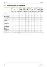
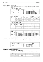
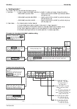
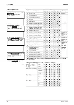
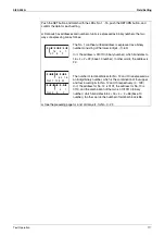
For setting items of (*1), refer to detailed information provided on page 118 onward.
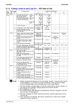
Setting item
Content and objective of setting
Overview of setting procedure
Serv
ic
e s
e
tti
ng
1
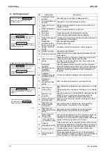
Indoor unit fan
forced H operation
Used to operate the indoor unit in the
stopped state in forced H operation mode.
Set No. 5 of "Setting mode 2" to indoor unit
forced fan H.
2
Indoor unit forced
operation
Used to operate the indoor unit in forced
operation mode.
Set No. 6 of "Setting mode 2" to indoor unit
forced operation mode.
3
Change of targeted
evaporating
temperature
(in cooling)
In cooling operation, used to change the
targeted evaporating temperature for
compressor capacity control.
Select high side or low side with No. 8 of
"Setting mode 2".
4
Change of targeted
condensing
temperature
(in heating)
In heating operation, used to change the
targeted condensing temperature for
compressor capacity control.
Select high side or low side with No. 9 of
"Setting mode 2".
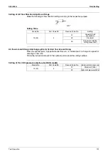
5
Setting of defrost
selection
Used to change a temperature at which the
defrost operation is initiated, thus making
the initiation easy or hard.
Select fast side or slow side with No. 10 of
"Setting mode 2".
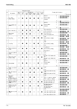
6
Setting of
sequential startup
Used to start units not in sequence but
simultaneously.
Set No. 11 of "Setting mode 2" to NONE.
7
Emergency
operation (*1)
If the compressor has a failure, used to
prohibit the operation of compressor(s)
concerned or outdoor unit(s) concerned
and to conduct emergency operation of the
system only with operable compressor(s)
or outdoor unit(s).
Make this setting while in "Setting mode 2".
For system with a single outdoor unit: Set
with No. 19 or 42.
For system with multiple outdoor units: Set
with No. 38, 39, or 40.
8
Additional
refrigerant
charging (*1)
If a necessary amount of refrigerant cannot
be charged due to the stop of outdoor unit,
operate the outdoor unit and then charge
refrigerant.
Set No. 20 of "Setting mode 2" to ON and
then charge refrigerant.
9
Refrigerant
recovery mode (*1)
Used to recover refrigerant on site.
With operations of indoor and outdoor units
prohibited, fully open the expansion valve
of the indoor and outdoor units.
Set No. 21 of "Setting mode 2" to ON.
10
Vacuuming mode
(*1)
Used to conduct vacuuming on site.
Fully open the expansion valves of the
indoor and outdoor units, and energize part
of solenoid valves. Use a vacuum pump to
conduct vacuuming.
Set No. 21 of "Setting mode 2" to ON.
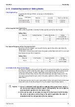
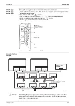
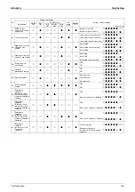
11
ENECUT test
operation
Used to forcedly turn ON the ENECUT.
(Be noted this mode is not functional with
the indoor unit remote controller turned
ON.)
Set No. 24 of "Setting mode 2" to ON.
12
Power transistor
check mode
Used for the troubleshooting of DC
compressors.
Inverter waveform output makes it possible
to judge whether a malfunction results from
the compressor or the PC board.
Set No. 28 of "Setting mode 2" to ON.
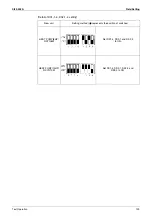
13
Setting of model
with spare PC
board
In order to replace the PC board by a spare
one, be sure to make model setting.
For this setting, set the DS2-2, -3, and-4
switches on the PC board to the model
concerned.
Содержание VRV II RXYQ8MY1K
Страница 18: ...Si39 502A Specifications 7 Part 2 Specifications 1 Specifications 8 1 1 Outdoor Units 8 1 2 Indoor Units 16...
Страница 53: ...Specifications Si39 502A 42 Specifications...
Страница 143: ...Field Setting Si39 502A 132 Test Operation...
Страница 247: ...Piping Diagrams Si39 502A 236 Appendix 1 Piping Diagrams 1 1 Outdoor Unit RXYQ8MY1K E YLK E RXYQ10MY1K E YLK E 3D049524...
Страница 250: ...Si39 502A Piping Diagrams Appendix 239 FXUQ BEVQ Indoor unit Connection Unit 4D037995F 4D034127B...
Страница 251: ...Piping Diagrams Si39 502A 240 Appendix FXAQ BEVQ Indoor unit Connection Unit 4D047084 4D034127B...
Страница 252: ...Si39 502A Piping Diagrams Appendix 241 FXLQ BEVQ Indoor unit Connection Unit 4D047084 4D034127B...
Страница 254: ...Si39 502A Wiring Diagrams for Reference Appendix 243 2 2 Field Wiring RXYQ8MY1K E YLK E RXYQ10MY1K E YLK E 3D040746J...
Страница 255: ...Wiring Diagrams for Reference Si39 502A 244 Appendix RXYQ16MY1K E YLK E RXYQ18MY1K E YLK E RXYQ20MY1K E YLK E 3D040747H...
Страница 257: ...Wiring Diagrams for Reference Si39 502A 246 Appendix 2 3 Indoor Unit FXCQ20M 25M 32M 63MVE 3D039556A...
Страница 258: ...Si39 502A Wiring Diagrams for Reference Appendix 247 FXCQ40M 50M 80M 125MVE 3D039557A...
Страница 259: ...Wiring Diagrams for Reference Si39 502A 248 Appendix FXFQ25M 32M 40M 50M 63M 80M 100M 125MVE 3D039600A...
Страница 260: ...Si39 502A Wiring Diagrams for Reference Appendix 249 FXKQ25M 32M 40M 63MVE 3D039564A...
Страница 261: ...Wiring Diagrams for Reference Si39 502A 250 Appendix FXDQ20N 25N 32N 40N 50N 63NVE with Drain Pump 3D045500B...
Страница 262: ...Si39 502A Wiring Diagrams for Reference Appendix 251 FXDQ20N 25N 32N 40N 50N 63NVET without Drain Pump 3D049604A...
Страница 263: ...Wiring Diagrams for Reference Si39 502A 252 Appendix FXSQ20M 25M 32M 40M 50M 63M 80M 100M 125MVE 3D039561A...
Страница 264: ...Si39 502A Wiring Diagrams for Reference Appendix 253 FXMQ40M 50M 63M 80M 100M 125MVE 3D039620A...
Страница 265: ...Wiring Diagrams for Reference Si39 502A 254 Appendix FXMQ200M 250MVE 3D039621A...
Страница 266: ...Si39 502A Wiring Diagrams for Reference Appendix 255 FXHQ32M 63M 100MVE 3D039801C...
Страница 267: ...Wiring Diagrams for Reference Si39 502A 256 Appendix FXAQ20M 25M 32M 40M 50M 63MVE 3D034206A...
Страница 269: ...Wiring Diagrams for Reference Si39 502A 258 Appendix FXUQ71M 100M 125MV1 3D044973...
Страница 270: ...Si39 502A Wiring Diagrams for Reference Appendix 259 FXAQ20MH 25MH 32MH 40MH 50MHV1 3D046348A...
Страница 271: ...Wiring Diagrams for Reference Si39 502A 260 Appendix FXLQ20MH 25MH 32MH 40MH 50MHV1 3D046787A...
Страница 272: ...Si39 502A Wiring Diagrams for Reference Appendix 261 BEVQ50MVE 3D046579A Notes...
Страница 273: ...Wiring Diagrams for Reference Si39 502A 262 Appendix BEVQ71M 100M 125MVE 3D044901A Notes...
Страница 285: ...Piping Installation Point Si39 502A 274 Appendix...
Страница 293: ...Method of Replacing The Inverter s Power Transistors and Diode Modules Si39 502A 282 Appendix...
Страница 307: ...Si39 502A iv Index...


