6
x
FlowSensor
FA ROTEX Solaris RPS4 -
04/2016
25
6.3.1 Fast access
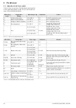
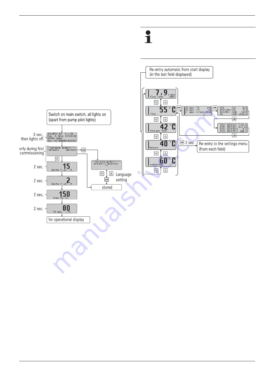
After switching on, the Solaris R4 regulator carries out a self-test,
where the display elements are switched on individually and the
setting parameters of the user level are displayed. The following
testing steps are carried out, and the results displayed for about
2 seconds (fig. 6-5):
– Immediately after switching on, the start display appears
which shows the installed software version and the serial
number of the device.
– During initial commissioning, the desired display language is
queried.
– After this, the current parameter settings which the user can
change are displayed.
– When the operating display appears, the self test is complete.
– The functions of the solar operating pump P
S
and their oper-
ating status lights can only be tested manually, for safety rea-
sons (see section 6.2.6).
6.3.2 Display during operation
During operation, the display shows the system temperatures,
maximum values, and calculated values. After the start display,
the Solaris R4 regulator is automatically in operating display
mode, an operating value is displayed and the associated
indicator lights up.
Ɣ
You can navigate between the four temperature measured
values and the flow measured value (see tab. 6-2 and
tab. 6-6) by pushing the arrow keys.
Ɣ
Pressing the Info key displays the maximum values and the
calculated values (see tab. 6-3).
The left-hand column of the display serves as a status display:
– "1" in the first line, solar operating pump P
S
normal operation
active.
– "2" in the 2nd line, solar operating pump P
S
active with maxi-
mum output (booster).
– "B" in the 3rd. line, burner block contact active (see
section 6.3.10) or a fault status (see section 7.2 "Trouble-
shooting").
– "H" in the 4th. line, manual operating mode.
6.3.3 Setup menu
The Solaris R4 regulator parameters are displayed and changed
in the menu.
Ɣ
Pressing the OK key once (>2 s) either activates the menu or
returns to the operating display. Briefly pressing the key
confirms a selection, opens the next menu item, or
displays [stored] for approx. 1 second after a value has been
changed.
Ɣ
In the selected parameter display, pressing the OK key
switches over to the parameter changing mode.
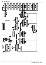
In the menu (fig. 6-7) the active menu path is displayed in the first
line, a cursor (">") in the left column indicates the next lower
menu path or a parameter. From here, you navigate to the re-
spective menu tree by means of the arrow keys: up (+ key) or
down (– key).
The set value can be changed in accordance with the arrow keys.
Briefly pressing an arrow key changes the value by one step, and
continuous pressing speeds up the change.
If the desired parameter has been changed and the entire pa-
rameter list has been scrolled down, you will arrive back to the se-
lection menu [choice 2/2] and from there into the operating
display (see fig. 6-7). The control unit starts working with the
changed parameter value(s) immediately. The display always re-
turns to the operating display mode after 10 minutes, provided
that no key is pressed during this time.
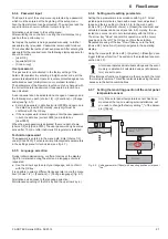
Fig. 6-5
Fast access
So long as no manual adjustments are made or an
event corresponding to tab. 7-2 produces a different
display, the actuated measured value or information
display remains active. It is activated again, even after
parameter changes or "Switching OFF-ON". If info parameters
are displayed, a measuring point check light is not activated.
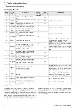
Fig. 6-6
Display during operation


