background image

SiBE81-909

Removal Procedure

Humidifying Air Purifier

83

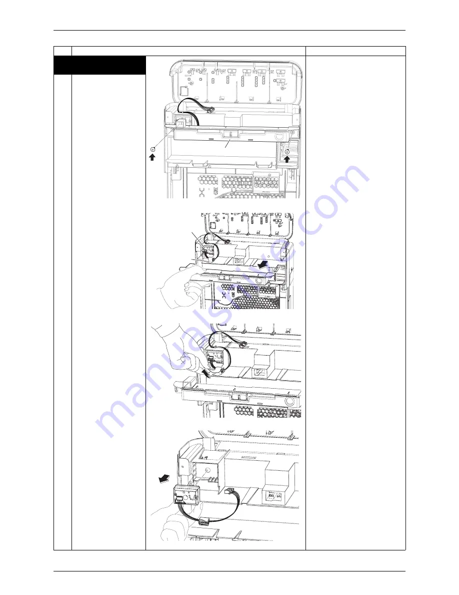
5. Removal of the dust 

sensor

1

Remove the 2 screws 
and remove the switch 
cover.

2

Remove the filament 
tape.

3

Pull out the dust 
sensor.

Step

Procedure

Points

(R9821)

Switch cover

(R9775)

Dust sensor

Filament 

tape

(R9777)

(R9776)

Содержание MCK75JVM-K

Страница 1: ...SiBE81 909 Humidifying Air Purifier...

Страница 2: ...25 5 7 Water Tank Preparations 26 5 8 Air Purifying Operation 28 5 9 Humidify and Air Purifying Operations 29 5 10 How to Operate with Remote Controller 30 5 11 How to Use the Recyclable Deodorizing C...

Страница 3: ...909 2 Humidifying Air Purifier 8 6 Removal of Power Supply Control PCB 84 8 7 Removal of Fan Motor 88 8 8 Removal of Power Cord 89 8 9 Removal of Proximity Switch 91 8 10 Removal of Humidifying Unit G...

Страница 4: ...Full Dust Collection Humidifying the room into all corners by high airflow rate and new vaporization humidifying system Humidification comparison with the humidifier Optimum humidification can be obta...

Страница 5: ...model When humidifying inturbomode 50 dB 7 5m3 min Sensitive Control Full Humidification Full Dust Collection 6 step airflow mode Top in the market Pollen operation When automatic airflow mode is sele...

Страница 6: ...which shows more than 1 000 times decomposing force for the general glow discharge and gets A prize of the Institute of Electrostatics Japan Streamer discharge Area where fast electron is generated El...

Страница 7: ...s product is for indoor use only Do not use in bathroom or outdoors as it is not water condensation proof Do not modify this product 2 2 Applicable Room Area Note The applicable room area is appropria...

Страница 8: ...rate Manual air purifying airflow rate Anti pollen mode air purifying Automatic humidifying airflow rate Manual humidifying airflow rate Anti pollen mode humidifying Humidity setting Turbo mode Negati...

Страница 9: ...ion filter Deodorizing method Flash streamer Titanium apatite photocatalytic filter Deodorizing catalyst Air filter Polypropylene net with catechin Bacteria filtering method Sign Dust sensor lamp 3 st...

Страница 10: ...t changes in accordance with indoor and outdoor temperature and humidity Measurement condition 20 C temperature 30 humidity JEM1426 3 Operating sound levels are the average of values measured at 1m aw...

Страница 11: ...Y SWITCH A2P PRINTED CIRCUIT BOARD FOR OPERATION H21P LED CLEANING OF UNIT2 ORANGE H38P LED ODOR SIGN GREEN RED S1C LIMIT SWITCH REGENERATION OF CARTRIDGE A3P PRINTED CIRCUIT BOARD FOR POWER SUPPLY H2...

Страница 12: ...9 Specifications Humidifying Air Purifier 11 4 4 Packaging Drawing C 2P241869A Deodorizing cartridge pack Wireless remote controller ASSY Pleated filter Power supply code Accessory bag ASSY Body Produ...

Страница 13: ...such as burning odors Continued use the unit in anything strange may lead to electric shock or fire because of overheating Contact the service shop If the power supply cord is damaged it must be repl...

Страница 14: ...neutral liquid detergent to clean the unit Use of chlorine or acidic detergents to clean the unit may generate harmful gas and harm health Keep cigarettes incense and other naked flames away from the...

Страница 15: ...ere that is hot such as near to heaters High temperatures may discolour or deform the unit Do not block the air inlets or air outlet with laundry cloth curtains etc Adhering lint may obstruct air pass...

Страница 16: ...nd of use will shorten the service life of the pre filter and pleated filter possibly leading to damage Do not use the unit to preserve artwork academic materials etc or for commercial or other specia...

Страница 17: ...d by the pre filter are positively charged to that they can be more easily absorbed by the negatively charged pleated filter Water tank Front panel Odor sensor Dust sensor Humidity sensor Temperature...

Страница 18: ...ck Coin Lock Pocket lock How to use the pocket lock Unlock Lock To lock turn to where the S meet Recyclable deodorizing cartridge Streamer pocket Use to regenerate the recyclable deodorizing cartridge...

Страница 19: ...er press and hold for about 2 seconds A short beep sound is emitted and the lamps go out Air purifying filter lamp This lamp lights when it is time to replace the pleated filter It flashes if more tim...

Страница 20: ...cord back in and start the unit ATTENTION Humidify ON OFF button Each time this button pressed the humidifying operation is turned on and off The lamp is lit while humidifying operation is ON Air pur...

Страница 21: ...as just a reference reading Dust sensor lamp Dust sensor detects the dirty state of the air The level of dirt is indicated by dust sensor lamp on 3 colors green orange and red When the lamp is lit on...

Страница 22: ...ation directly after setting the power plug 3 In case the operation is started again If the odor level remains constant without intensifying or weakening the sensor may not detect even strong odors Th...

Страница 23: ...ot change unplug the power supply cord wait at least 3 seconds plug the power supply cord back in and try the operation again from the beginning 3 After changing the setting press A short beep sound i...

Страница 24: ...ot use the unit in the following places In contact with walls furniture curtains etc Contacted objects may stain or deform On thick pile carpets or bedding The unit may tilt possibly spilling water or...

Страница 25: ...tape If mixed with other metal or batteries heat explosion or combustion may occur Battery The included coin type battery is prepared for initial use They will be consumed within 1 year from the manuf...

Страница 26: ...ormance drops if the pleated filter is attached backwards 1 Remove the front panel Push the 2 projections left and right inwards and pull the front panel upwards and remove 2 Remove the water tank Hol...

Страница 27: ...feration 1 Open the cap on the water tank 2 Add water to the tank and close the cap Add water somewhere that can be wet if spilled Before adding the actual water to use in humidification add a small a...

Страница 28: ...ojections on the unit into the grooves 2 locations at the bottom of the main unit and press UNIT1 into the main unit 3 Restore the water tank Holding the water tank by the handle fit the tank into the...

Страница 29: ...This mode is recommended when sleeping The airflow rate is changed every 5 minutes to create gentle air currents so as to catch the pollen before settling on the floor The default settings are air pur...

Страница 30: ...rflow rate setting cannot be select To set the airflow rate set the humidify setting CONT Humidifying capacity increases alongside airflow rate When set to auto airflow rate is automatically adjusted...

Страница 31: ...ty state of the air 3 To manually switch the airflow rate Press Each time it is pressed the airflow rate switches as shown below allowing you to choose your desired flow The setting LL Quiet is a very...

Страница 32: ...ill switch as shown below Operating panel lamps Front indicator lamps Only the front indicator lamps go completely off 10 To prevent incorrect operation Press for 2 seconds Stops the function of the b...

Страница 33: ...ridge The recyclable deodorizing cartridge is not intended for use in spacious places and places of strong smell therefore use the main unit in those cases The air purifier may be used with the recycl...

Страница 34: ...d without running the air purifier by simply plugging into the power supply cord Regeneration stops automatically for safety reasons if the front panel is opened or the power supply cord is unplugged...

Страница 35: ...28 3 Pre filter Once every 2 weeks Page 29 4 Plasma ionizer If the UNIT1 lamp lights Page 33 34 5 Streamer unit If the UNIT2 lamp lights Page 33 34 6 Pleated filter If the Air purifying filter lamp li...

Страница 36: ...Dust Odor sensors and Temperature Humidity sensors XPage 27 5 Streamer unit UNIT2 XPage 33 34 7 Deodorizing catalyst unit XPage 28 6 Pleated filter front white back blue XPage 30 31 1 Front panel XPag...

Страница 37: ...ot be started Front panel cleaning Sensor air inlet cleaning Dust odor temperature and humidity sensors Air inlets Air inlets NOTE Rear of front panel Projection Top hole Be careful not to damage thes...

Страница 38: ...st with a vacuum cleaner Do not rub the front surface For procedures on removing and restoring the deodorizing catalyst unit see Pleated filter replacement Deodorizing catalyst unit Recyclable deodori...

Страница 39: ...l the filter to the front and disengage the tabs 4 locations on the left and right of the pre filter from the holes 4 locations on the left and right of UNIT1 For stubborn dirt wash with a soft bristl...

Страница 40: ...g the deodorizing catalyst unit by the handle pull the deodorizing catalyst unit upwards and out of the unit If the deodorizing catalyst unit is dirty suck up dust with a vacuum cleaner If the plate i...

Страница 41: ...See the ATTENTION on page 38 The pleated filter does not need replacing until the Air purifying filter lamp lights or flashes Replace the pleated filter if the Air purifying filter lamp lights or fla...

Страница 42: ...T1 pre filter water tank and front panel XPage 29 The opposing pole plates have no required right and left direction and can be attached either side of ionizing frame Attach them so that the arrow is...

Страница 43: ...recesses and places where fingers do not fit with a cotton swab etc Do not leave any lint from cleaning cloths behind Lint may lead to malfunction CAUTION Before performing maintenance stop the unit a...

Страница 44: ...n small quantities the UNIT1 and UNIT2 lamps do not go out after cleaning therefore dry thoroughly in a shade Reattach the streamer unit as before 2 Ionized wire 8 locations Remove dirt from ionized w...

Страница 45: ...ent indicated in the cleaner s instructions 4 Immerse the humidifying filter in the water and soak for about 30 60 minutes 5 Rinse in running water Use clean water Repeat 2 3 times with fresh water ea...

Страница 46: ...the antibacterial anti mildew and slime prevention effects are disabled Depending on the water quality and environment of usage the accumulated water in the humidifying tray may be discolored by scale...

Страница 47: ...ssed and held for 2 seconds Tuck the humidifying filter underneath the tabs 6 locations on the waterwheel so that it does not stick out from the waterwheel For replacement humidifying filters contact...

Страница 48: ...ical symbol can be printed beneath the symbol This chemical symbol means that the battery contains a heavy metal above a certain concentration Possible chemical symbols are Pb lead 0 004 Hg mercury 0...

Страница 49: ...lacement guideline Every year for about 7 years in total 2 Appearance color White front blue back KAC998A4E Non woven fabric electrostatic 7 C 3JHB13523 KNME998A4E 47 pleats 1 pleat 20 20 hole 2 4 0 S...

Страница 50: ...Accessories Humidifying Air Purifier 49 6 1 3 Front Panel for Russia BCK75J BD Bordeaux or Black FRONT PANEL OPTION Black 502 5 4 395 4 46 5 Specifications Model Color and Quantity BCK75J BD Bordeaux...

Страница 51: ...ken Pulled out Operating panel Lighting UNIT1 Plasma ionizer UNIT2 Streamer unit Clean as above Lighting or Flash Replace the humidifying filter or the air purifying filter pleated filter Then press a...

Страница 52: ...time The check lamp flashes too Something is obstructing the air outlet Unplug the power supply cord remove the obstruction plug the power supply cord back in and start the unit Operating panel EMPTY...

Страница 53: ...1 4 8 If all 3 lamps flash at the same time Trouble has occurred in electrical parts Contact the service shop Operating panel CONT If a long beep sounds 3 times and the 4 lamps flash at the same time...

Страница 54: ...Are the projections on the backside of the front panel damaged Set the unit on a flat floor and press the ON OFF button Set the humidifying tray properly Securely set it XPage 18 Check the projection...

Страница 55: ...nal room may smell Let the unit run for a while Clean it XPage 29 36 Ventilate the room or let the unit run with air flow promoted in the room The UNIT1 lamp does not go out or immediately lights agai...

Страница 56: ...flashing the humidifying tray is not properly installed Install the tray properly XPage 35 36 If none of the front indicator lamps or the lamps on the operating panel light the front panel may be open...

Страница 57: ...be cleaned Question Can I wash the deodorizing catalyst unit Is replacement necessary Answer The deodorizing catalyst unit cannot be washed The unit will be ruined Remove the deodorizing catalyst unit...

Страница 58: ...tection 3 Malfunction Deci sion conditions 4 Supposed Causes The unit is not turned on Unspecified voltage is used The front panel is broken The protrusion on the front panel is broken The power suppl...

Страница 59: ...fying tray is removed or not installed The humidifying tray is deformed or broken The connector is improperly con nected The limit switch harness is broken The limit switch is defective Caution Be sur...

Страница 60: ...ci sion conditions 4 Supposed Causes Wrong diagnosis Red lighting of the odor dust sen sor during detecting dust or mois ture in the air was decided as failure The sensor is defective The display PCB...

Страница 61: ...lity of the fan motor is detected by revolutions with the Hall IC while the fan motor is running 3 Malfunction Deci sion conditions When the fan motor is not revved up 4 Supposed Causes The fan motor...

Страница 62: ...o to on P 64 2 Method of Mal function Detection 3 Malfunction Deci sion conditions 4 Supposed Causes The flat cable is improperly con nected The display PCB is defective The operation PCB is defective...

Страница 63: ...Malfunction Deci sion conditions 4 Supposed Causes The humidity sensor PCB is defective The display PCB is defective The operation PCB is defective The connector is improperly con nected The harness i...

Страница 64: ...ected 3 Malfunction Deci sion conditions When the zero cross cannot contin uously be detected for about 10 sec onds 4 Supposed Causes The connector is improperly con nected The power supply PCB is def...

Страница 65: ...of the dust correction HVU is improperly connected When the air purifying filter lamp blinks The dust sensor is at fault or improperly connected The odor sensor is at fault The humidifying sensor is...

Страница 66: ...all to avoid making stain For details see the operation manual Operating panel and front indicator 2 Removal the front panel 1 Press the right and left projections one for each in the upper section of...

Страница 67: ...er main unit 3 Removal of the water tank 1 Lift the water tank up towards yourself and remove When assembling insert the water tank into the lower hole Do not charge the water tank with hot water high...

Страница 68: ...he humidifying filter 3 When replacing the humidifying filter remove the center pivot The humidifying filter for replacement is an optional accessary 4 Remove the humidifying filter by releasing the 6...

Страница 69: ...by a flat driver and lift the float switch up to remove Do not disassemble the float switch 7 Removal of the silver ion cartridge 1 Press the hook of the silver ion cartridge by a flat driver and lift...

Страница 70: ...and undo the right and left hooks 4 in total When assembling the pre filter put the 4 right and left hooks of the pre filter over the 4 holes in the plasma ionizer unit and insert the hooks into the...

Страница 71: ...own support the humidifying air purifier while removing the plasma ionizer unit There is a hook on the each side 1 Hold the grips of the plasma ionizer unit Pull the unit toward yourself and lift up t...

Страница 72: ...ir purifier 1 Hold the grips of the deodorizing catalyst unit Pull the unit toward yourself and lift up to remove When assembling insert the hooks of the deodorizing catalyst unit into the 4 lower hoo...

Страница 73: ...2 Remove the pleated filter from the right and left projections 10 in total 3 Release the 3 upper hooks and remove the pleated filter 4 Release the lower hook and remove the pleated filter Step Proce...

Страница 74: ...section after removing the pleated filter 2 Raise the deodorizing catalytic filter from the base and remove the filter When assembling the lower section of the filter in the frame bend and compress th...

Страница 75: ...r turning off all power supplies before disassembling work Step Procedure Points 1 Unlock the streamer pocket 2 Remove the recyclable deodorizing cartridge Do not place the recyclable deodorizing cart...

Страница 76: ...ning Be sure to wait 10 minutes or more after turning off all power supplies before disassembling work Step Procedure Points 1 Pull out the streamer unit Caution Do not disassemble the streamer electr...

Страница 77: ...do the 2 hooks and lift the opposing pole plate to detach The opposing pole plate has the same shape in 4 directions 2 Pinch and detach the ionizing wires with pincers Caution Be careful not to get yo...

Страница 78: ...iBE81 909 Removal Procedure Humidifying Air Purifier 77 3 Remove the 3 screws from each of right and left mounting frames and remove the mounting frames Step Procedure Points R9810 Ionizing wires R981...

Страница 79: ...ning Be sure to wait 10 minutes or more after turning off all power supplies before disassembling work Step Procedure Points 1 Removal of the operation sign cover 1 Remove the 2 screws from the back s...

Страница 80: ...et 5 Slide the back panel When the back panel is not removed the operation sign cover can be lifted up but not be removed 6 Lift up the operation sign cover When assembling insert the edge of the cove...

Страница 81: ...until the silver part cannot be found 1 Disconnect the linkage connector from the power supply control PCB 2 Remove the 2 screws S1 Dust sensor S3 Humidity sensor S128 Connector for power supply contr...

Страница 82: ...nsor S1 6 Disconnect the connector for the humidity sensor S3 7 Disconnect the connector for Signal receiver S4 8 The figure shows the operation PCB S1 Dust sensor S3 Humidity sensor S4 Signal receive...

Страница 83: ...Release the 3 hooks and remove the display PCB 2 The figure shows the display PCB 4 Removal of the humidity sensor PCB 1 Release the 2 hooks and remove the humidity sensor PCB 2 The figure shows the h...

Страница 84: ...ing Air Purifier 83 5 Removal of the dust sensor 1 Remove the 2 screws and remove the switch cover 2 Remove the filament tape 3 Pull out the dust sensor Step Procedure Points R9821 Switch cover R9775...

Страница 85: ...on PCB Refer to the removal of the display PCB and the operation PCB 1 Remove the 5 screws of the rear panel 2 Disconnect the connector for the limit switch 3 Remove the 2 screws of the electric equip...

Страница 86: ...pment box cover 2 Removal of the power supply control PCB 1 The figure shows the wiring of the wire harness 2 Disconnect the joint connector 3 Disconnect the each connector Step Procedure Points R9825...

Страница 87: ...6 The figure shows the power supply control PCB S102 Fan motor S108 Safety switch S113 Float proximity sensor switch S114 Limit switch regeneration of cartridge S115 Limit switch tray S116 Motor for t...

Страница 88: ...ction green Remove the high voltage PCB by releasing the 2 hooks and removing the 1 screw 3 The figure shows the high voltage PCB a 1Harness for electrostatic earth b 2Harness red c 3Harness white d 4...

Страница 89: ...he harness retainer toward yourself and lift it up to remove When assembling put part A first in the groove and then slide part B along the way When assembling make sure that the harness is not too ti...

Страница 90: ...after turning off all power supplies before disassembling work Step Procedure Points 1 Removable of the power cord 1 Remove the 3 screws from the casing frame Remove the power cord 2 Remove the 3 scre...

Страница 91: ...the power cord Step Procedure Points R9840 R9841 Humidifying rotor ASSY Water pan ASSY Put the wire harness through the groove of the casing Put the wire harness through the groove of the casing Wire...

Страница 92: ...rk Step Procedure Points 1 Removal of the proximity switch 1 Remove the screw and remove the drip proof plate 2 Remove the screw and remove the proximity sensor 3 Disconnect the connector of the limit...

Страница 93: ...ing unit gear to remove 2 Disconnect the connector S116 3 Remove the 2 screws and remove the humidifying rotor 2 Removal of the safety switch 1 Remove the safety switch R9845 Humidifying unit gear Whi...

Страница 94: ...ns designs and other content appearing in this brochure are current as of May 2009 but subject to change without notice SiBE81 909 Printed in Japan 05 2009 B AK SiBE81 909 Service Manual Humidifying A...

Отзывы: