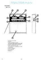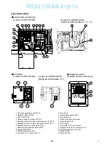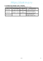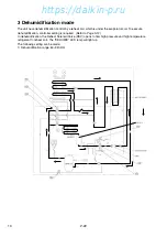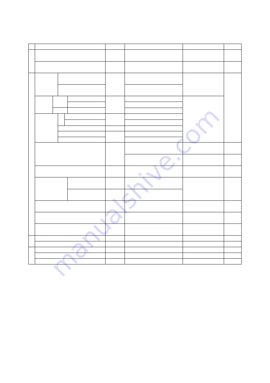
Device name
Actuation
Set point
Detection method
Symbol
High-pressure switch
OFF
2400kPa (24.47kg/cm
2
) High-pressure
switch
HPS
ON 1900kPa
(19.37kg/cm
2
)
Water pressure switch
OFF
98kPa (1.0kg/cm
2
)
Water pressure switch
WPS
(optional)
ON 39kPa
(0.4kg/cm
2
)
Chilled mode
ON
+30.0°C ~ –10.0°C
Set point temperature
EC
Mode selection
(+86.0°F ~ –14.0°F)
Frozen mode
–10.1°C ~ –30.0°C
(13.82°F ~ –22.0°F)
Delay Fan Change-over for Hi/Lo ON 10
seconds
timer
After defrosting
60
seconds
Compressor At starting
3 seconds
Defrosting Short
ON
4
hours
※
1
timer
Long
3, 6, 9, 12, 24 and 99 hours(
※
2)
Back-up
OFF 90
minutes
In-range masking
90 minutes
※
3
Out-range guard
ON
30 minutes
Defrosting termination set point
OFF
30˚C (86°F)
Evaporator outlet
EOS
Reset
tempertature
sensor
15˚C
(59°F)
※
4
Return air temperature
RS, DRS
sensor
High-pressure control for Condenser fan OFF
800kPa
(8.2kg/cm
2
)
※
7
High-pressure transducer
HPT
(※
Frozen only)
ON
1000kPa (10.2kg/cm
2
)
Discharge gas
Pull down
OFF
135˚C (275°F)
Discharge gas
DCHS
temperature
LPT>50kpa
Reset
After 3 minutes elapsed
temperature sensor
protection LPT
≦
50kpa OFF
128˚C
(262°F)
set
point
Reset
After 3 minutes elapsed
Overcurrent protection set point (Cutout)
OFF
26.0A
PT/CT board
CT2
Reset
After 3 minutes elapsed
Current control
Control
50Hz : 16.1A
PT/CT board
CT1
60Hz : 17.4A
High pressure control
Control 2300 to 2350 kPa
High pressure sensor
HPT
(23.5 to 24.0 kg/cm
2
)
Circuit
breaker
OFF 30A
CB
Fuse
OFF 5A,
10A
※
5
Fu
Evaporator fan motor thermal protector
OFF
132˚C (270°F)
Condenser fan motor thermal protector
OFF
135˚C (275°F)
MTP
Compressor motor thermal protector
OFF
140˚C (284°F)
CTP
8
2-9
2.3 Set point of functional parts and protection devices
Electronic controller
Initiation
Current
Motor
Pressure s
w
itch
(
※
1) When Return air (RS) is lower than –20˚C, defrost starts every 6 hours.
(
※
2) When "99" hours is selected, refer to on demand defrost in 2.5.3. (TR01-09A)
(
※
3) When Inside set point is –20.0˚C or Lower, In-range masking is 120min.
(
※
4) If defrost is initiated when inside temperature is out rangle area. (= In-range LED is not light), this condition is added to
finish defrost. Refer to "Defrosting termination" in 2.5.3. (TR01-09A)
(
※
5) Refer to "Fuse Protection table" in 7.11. (TR01-09A)
(
※
7) When dehumidification is ON in dehumidification mode, the setting figure may change between 900~2100kPa
automatically (Refer to "High Pressure Control" Page 2-17/TR01-09A)
04-08̲LXE10E-A33.indd 8
04-08̲LXE10E-A33.indd 8
07.3.6 11:23:42 AM
07.3.6 11:23:42 AM
https://daikin-p.ru
Содержание LXE10E-A33
Страница 18: ...17 9 2 Schematic wiring diagram LXE10E A33 https daikin p ru...
Страница 19: ...18 9 3 Stereoscopic wiring diagram LXE10E A33 BLK BLU GRN GRY RED WHT BRN YLW https daikin p ru...
Страница 59: ...Parts related with option 3 Others 58 K2 K5 K3 K4 K1 Indoor fan guard Evaporator coil K6 https daikin p ru...
Страница 71: ...MEMO https daikin p ru...


