2
*Differences from standard model service manual (TR01-09A) are marked with
☆
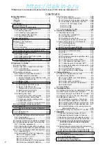
CONTENTS
3.10 Chartless function ..................................... 3-56
3.10.1 Chart indication function .................... 3-56
3.10.2 P code (Pull down time indication) ..... 3-58
3.10.3 Chartless code display function ......... 3-59
3.10.3.1 List of chartless code .................. 3-59
3.10.3.2 H-code ........................................ 3-60
3.10.3.3 d-code: ........................................ 3-62
3.11 Communication modem ............................ 3-63
4. Service and Maintenance ................................. 4-1
4.1 Maintenance service .................................... 4-1
4.1.1 Collection of refrigerant .......................... 4-1
4.1.2 Gauge manifold ..................................... 4-1
4.1.3 Automatic pump down ........................... 4-3
4.1.4 Refrigerant recovery and charge ........... 4-5
4.2 Main components and maintenance ............. 4-9
4.2.1 Scroll compressor .................................. 4-9
4.2.2 Fan and fan motor ................................ 4-11
4.2.3 PT and CT board (EC9756) ................. 4-12
4.2.4 Electronic expansion valve .................. 4-14
4.2.5 Suction modulation valve ..................... 4-15
4.2.6 Drier ..................................................... 4-16
4.2.7 Solenoid valve ...................................... 4-17
4.2.8 Discharge pressure regulating valve .... 4-18
4.2.9 Check valve ......................................... 4-18
4.2.10 High-pressure switch (HPS) .............. 4-19
4.2.11 Low pressure transducer (LPT) ......... 4-19
4.2.12 High pressure transducer (HPT) ........ 4-20
4.2.13 Air-cooled condenser and evaporator ... 4-20
4.2.14 Fusible plug ....................................... 4-21
4.2.15 Liquid/moisture indicator .................... 4-21
4.2.16 Evacuation and dehydrating .............. 4-22
5. Optional Devices ............................................... 5-1
5.1 Electronic temperature recorder ................... 5-1
5.2 USDA transportation ..................................... 5-3
5.2.1 Type of USDA sensor/receptacle ........... 5-3
5.2.2 Initial setting ........................................... 5-3
5.2.3 USDA sensor calibration ........................ 5-3
5.2.4 USDA transportation requirement .......... 5-3
5.2.5 USDA report .......................................... 5-3
5.3 TransFRESH ................................................. 5-5
6. Troubleshooting ................................................ 6-1
6.1 Refrigeration system and electrical system ... 6-1
6.2 Alarm codes on electronic controller ............ 6-4
6.3 Troubleshooting for automatic PTI (J-code) ... 6-9
6.4 Diagnosis based on the recording chart ..... 6-11
6.5 Emergency operation ................................. 6-14
6.5.1 Emergency operation of controller ....... 6-14
6.5.2 Short circuit operation of controller ...... 6-15
6.5.3 Opening adjustment of electronic expansion valve ... 6-16
6.5.4 Opening adjustment of suction modulation valve: ... 6-17
6.5.5 Automatic Back up for supply/ return air
temperature sensors ............................ 6-18
6.6 Troubleshooting for automatic PTI (J-code) ... 6-19
7. Appendix ........................................................... 7-1
7.1 Standard tightening torques for bolts ............ 7-1
7.2 Standard tightening torque for flare nut ........ 7-1
7.3 Resistance of motor coil and solenoid valve coil ... 7-1
7.4 HFC134a, temperature-vapor pressure characteristics table ... 7-2
7.5 Temperature conversion table and temperature sensor
(SS/RS/DSS/DRS/RSS/RRS/EIS/EOS/SGS/AMBS)
characteristics table ............................................ 7-3
7.6 Temperature conversion table and temperature
sensor (DCHS) characteristics table ............... 7-4
7.7 High pressure transducer characteristics table ... 7-4
7.8 Low pressure transducer characteristics table ... 7-4
7.9 Piping diagram .............................................. 7-5
7.10 Pilot lamps and monitoring circuit ............... 7-6
7.11 Fuse protection table .................................. 7-7
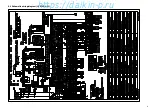
7.12 Schematic wiring diagram .......................... 7-9
7.13 Stereoscopic wiring diagram .................... 7-10
Safety Precautions
• Danger ................................................................ 3
• Warning ............................................................... 4
• Caution ................................................................ 5
1. Introduction ....................................................... 1-1
1.1 Operation range ............................................ 1-1
1.2 Basic Names of components ........................ 1-1
1.3 Basic operation of refrigeration unit .............. 1-2
1.3.1 Starting operation .................................. 1-2
1.3.2 Checking during operation ..................... 1-3
1.3.3 Procedure after operation ...................... 1-3
1.3.4 Adjust the ventilation .............................. 1-4
2. General description .......................................... 2-1
2.1 Main specifications ....................................... 2-1
2.2 Names of components .................................. 2-2
2.2.1 Outside .................................................. 2-2
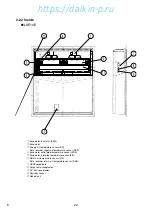
2.2.2 Inside ..................................................... 2-4
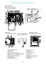
2.2.3 Control box ............................................ 2-6
2.3 Set point of functional parts and protection devices ... 2-9
2.4 Operating pressure and running current ..... 2-10
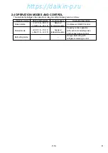
2.5 Operation modes and control ..................... 2-14
2.5.1 Frozen mode ........................................ 2-15
2.5.2 Chilled and partial frozen mode ........... 2-17
2.5.3 Defrosting mode .................................. 2-19
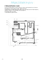
2.5.4 Dehumidification mode (Optional) ....... 2-22
2.5.5 Common control .................................. 2-23
3. Electronic Controller ........................................ 3-1
3.1 Function table ............................................... 3-1
3.2 Basic operation of electronic controller ......... 3-3
3.2.1 Control panel ......................................... 3-3
3.2.2 Operation mode and control .................. 3-5
3.3 Operation procedure ..................................... 3-6
3.3.1 Operation procedure flow chart ............. 3-6
3.3.2 Mode operation procedure ..................... 3-9
1. Current (Operation state) indication mode ... 3-9
2. Operation setting mode ........................ 3-10
3. Battery mode ....................................... 3-11
4. Mode operation .................................... 3-12
5. LED display light-OFF mode ................ 3-14
6. Sensor indication mode ....................... 3-15
7. Temperature record scroll mode .......... 3-18
8. Alarm record scroll mode ..................... 3-21
9. PTI record scroll mode ......................... 3-23
3.3.3 Setting flow chart ................................. 3-24
10. Optional function setting mode .......... 3-26
11. Basic function setting mode ............... 3-27
12. Optional condition setting mode ......... 3-29
13. Input data mode ................................. 3-31
14. Controller software download mode ... 3-32
3.4 Alarm display and back-up function ............ 3-33
3.4.1 Alarm list .............................................. 3-33
3.4.2 Back-up operation at sensor malfunction ... 3-34
3.5 Battery ........................................................ 3-36
3.5.1 Specifications ....................................... 3-36
3.5.2 Function ............................................... 3-36
3.6 Information interchange with personal computer ... 3-37
3.6.1 Data logging ......................................... 3-38
3.6.2 Software configuration ......................... 3-39
3.7 Inspection procedure for the electronic controller ... 3-41
3.8 Controller replacement and the initial setting ... 3-42
3.8.1 Controller replacement ........................ 3-42
3.8.2 Initial setting & operation procedure .... 3-43
3.8.3 Initial setting table into spare controller ... 3-44
3.9 PTI (Pre-Trip Inspection) and periodic inspection ... 3-45
3.9.1 Inspection item ..................................... 3-46
3.9.2 Automatic PTI (Pre-Trip Inspection) ..... 3-49
3.9.2.1 PTI selection mode ....................... 3-50
3.9.2.2 Short PTI (S.PTI) .......................... 3-51
3.9.2.3 Full PTI (F.PTI) .............................. 3-52
3.9.2.4 Alarm list during PTI (Pre-Trip Inspection) ... 3-53
3.9.2.5 Manual check (M.CHECK) ............ 3-54
☆
☆
☆
☆
☆
☆
☆
☆
☆
☆
01-02̲LXE10E-A33.indd 2
01-02̲LXE10E-A33.indd 2
07.2.1 10:51:55 AM
07.2.1 10:51:55 AM
https://daikin-p.ru
Содержание LXE10E-A33
Страница 18: ...17 9 2 Schematic wiring diagram LXE10E A33 https daikin p ru...
Страница 19: ...18 9 3 Stereoscopic wiring diagram LXE10E A33 BLK BLU GRN GRY RED WHT BRN YLW https daikin p ru...
Страница 59: ...Parts related with option 3 Others 58 K2 K5 K3 K4 K1 Indoor fan guard Evaporator coil K6 https daikin p ru...
Страница 71: ...MEMO https daikin p ru...


