


28
6 iLINQ Network Guide
The iLINQ network feature allows the networking of up to 10 iLINQ controllers together on a TCP/IP network. This feature
makes it possible to monitor key data points via summary pages for each networked iLINQ controller.
6.1
iLINQ Network Settings & Terminology
Figure 30 provides an overview of the settings and terminology associated with the iLINQ network. The most important
distinction being local and remote iLINQ controllers. The local controller receives the space temperature and space
humidity from the room terminal via serial pLAN communication. The remote controllers are networked via Ethernet
cabling and are not connected to the room terminal via serial pLAN communication. When configured, data points from
the remote controllers are shared with the local controller via the Ethernet TCP/IP connection. The iLINQ summary data
is transferred from the local iLINQ controller to the room via the pLAN serial communication.
For successful implementation of the iLINQ network, the room terminal and iLINQ controllers must be assigned unique
static IP addresses on the same network. Refer to Figure 30 for an example of iLINQ network architecture. The IP settings
are for example only and are subject to change to meet installation requirements.
For controller identification purposes, it is recommended that each iLINQ DDC Controller is assigned a unique Unit
Number. The Unit Number can be assigned by pressing the enter key twice on the homescreen of each controllers
onboard LCD.
Local
Remote
Figure 30 - Room Terminal System Information Page
6.2
iLINQ Network Configuration
The iLINQ configuration process involves entering the IP addresses of remote controllers into the local controller. The
iLINQ network can be configured via the room terminal, the local controller’s web interface, or the local controller’s
onboard LCD. For web interface and onboard LCD instructions, refer to the iLINQ DDC User Manual.
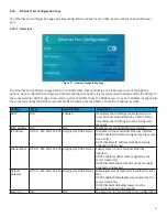
To configure the iLINQ network via the room terminal, tap the iLINQ network icon on the service menu page. Data for
the iLINQ Network Configuration Page is organized in a scrollable table. With the exception of the first row, each row
represents a node address on the iLINQ network. The first row displays the IP address of the local controller. Once an
IP address of a remote controller is entered into a blank node address row, tap the enable toggle switch and wait for
the status to update. If successful communication is established the status will appear as “Online”. If not, the status will
appear as “Error” and the network settings should be verified.