


ESIE10-01
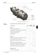
Maintenance
5–9
3
5
1
5
■
N.B.:
As the load changes and the number of active fans changes, subcooling also changes and
takes a few minutes to stabilise. In any case, it must never go below 3°C in any condition.
Furthermore, the subcooling value may change slightly as the water temperature and suction
superheating vary.
One of the two following scenarios can arise in a machine without refrigerant:
1.
If the refrigerant level is slightly low, the flow of bubbles can be seen through the liquid sight
glass. Replenish the circuit as described in the replenishment procedure.
2.
If the gas level in the machine is moderately low, the corresponding circuit could have some low
pressure stops. Replenish the corresponding circuit as described in the replenishment proce-
dure.
Refrigerant
replenishment
procedure
1.
If the machine has lost refrigerant, it is necessary to first establish the causes before carrying out
any replenishment operation. the leak must be found and repaired. Oil stains are a good indica-
tor, as they can appear in the vicinity of a leak. However, this is not necessarily always a good
search criterion. Searching with soap and water can be a good method for medium to large
leaks, while an electronic leak detector is required to find small leaks.
2.
Add refrigerant to the system through the service valve on the evaporator inlet pipe.
3.
The refrigerant can be added under any load condition between 25 and 100% of the circuit. Suc-
tion superheating must be between 4 and 6°C.
4.
Add enough refrigerant to fill the liquid sight glass entirely so that no flow of bubbles can be seen
any more. Add an extra 2 ÷ 3 kg of refrigerant as a reserve, to fill the subcooler if the compressor
is operating at 50 - 100% load.
5.
Check the subcooling value by reading the liquid pressure and the liquid temperature near the
expansion valve. The subcooling valve must be between 4 and 8°C and 10 and 15°C for the
machines with economiser. The subcooling value will be lower at 75 - 100% load and greater at
50% load.
6.
With ambient temperature higher than 16°C, all fans must be on.
7.
Overcharging the system will cause a rise in the compressor's discharge pressure, due to
excessive filling of the condensation section tubes.
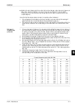
Pressure/Temperature table of the HFC-134a
°C
Bar
°C
Bar
°C
Bar
°C
Bar
-14
0.71
12
3.43
38
8.63
64
17.47
-12
0.85
14
3.73
40
9.17
66
18.34
-10
1.01
16
4.04
42
9.72
68
19.24
-8
1.17
18
4.37
44
10.30
70
20.17
-6
1.34
20
4.72
46
10.90
72
21.13
-4
1.53
22
5.08
48
11.53
74
22.13
-2
1.72
24
5.46
50
12.18
76
23.16
0
1.93
26
5.85
52
13.85
78
24.23
2
2.15
28
6.27
54
13.56
80
25.33
4
2.38
30
6.70
56
14.28
82
26.48
6
2.62
32
7.15
58
15.04
84
27.66
8
2.88
34
7.63
60
15.82
86
28.88
10
3.15
36
8.12
62
16.63
88
30.14
Содержание EWAD620-C17C-SL
Страница 2: ......
Страница 8: ...ESIE10 01 1 2 Part 1 System Outline 3 1 1 5 ...
Страница 111: ...ESIE10 01 General Outline Part 1 System Outline 1 105 3 1 4 5 1 36 1 Power Compressor 1 2 ...
Страница 112: ...General Outline ESIE10 01 1 106 Part 1 System Outline 3 1 1 4 5 1 36 2 Power Compressor 3 ...
Страница 113: ...ESIE10 01 General Outline Part 1 System Outline 1 107 3 1 4 5 1 36 3 Kit Pumps ...
Страница 114: ...General Outline ESIE10 01 1 108 Part 1 System Outline 3 1 1 4 5 1 36 4 Circuit Fan Power Supply 1 ...
Страница 115: ...ESIE10 01 General Outline Part 1 System Outline 1 109 3 1 4 5 1 36 5 Circuit Fan Power Supply 1 ...
Страница 116: ...General Outline ESIE10 01 1 110 Part 1 System Outline 3 1 1 4 5 1 36 6 Circuit Fan Power Supply 2 ...
Страница 117: ...ESIE10 01 General Outline Part 1 System Outline 1 111 3 1 4 5 1 36 7 Circuit Fan Power Supply 2 ...
Страница 118: ...General Outline ESIE10 01 1 112 Part 1 System Outline 3 1 1 4 5 1 36 8 Circuit Fan Power Supply 3 ...
Страница 119: ...ESIE10 01 General Outline Part 1 System Outline 1 113 3 1 4 5 1 36 9 Circuit Fan Power Supply 3 ...
Страница 120: ...General Outline ESIE10 01 1 114 Part 1 System Outline 3 1 1 4 5 1 36 10 Unit Control Circuit Power Supply ...
Страница 121: ...ESIE10 01 General Outline Part 1 System Outline 1 115 3 1 4 5 1 36 11 Analog Inputs Output Board ...
Страница 122: ...General Outline ESIE10 01 1 116 Part 1 System Outline 3 1 1 4 5 1 36 12 Digital Inputs Board ...
Страница 123: ...ESIE10 01 General Outline Part 1 System Outline 1 117 3 1 4 5 1 36 13 Digital Outputs Board ...
Страница 124: ...General Outline ESIE10 01 1 118 Part 1 System Outline 3 1 1 4 5 1 36 14 Digital Outputs Board ...
Страница 125: ...ESIE10 01 General Outline Part 1 System Outline 1 119 3 1 4 5 1 36 15 Extension Control Fans 1 2 ...
Страница 126: ...General Outline ESIE10 01 1 120 Part 1 System Outline 3 1 1 4 5 1 36 16 Extension Control Fans 3 ...
Страница 127: ...ESIE10 01 General Outline Part 1 System Outline 1 121 3 1 4 5 1 36 17 Extension Control Fans 4 ...
Страница 128: ...General Outline ESIE10 01 1 122 Part 1 System Outline 3 1 1 4 5 1 36 18 Expansion Input Output Unit Alarm Limiting ...
Страница 129: ...ESIE10 01 General Outline Part 1 System Outline 1 123 3 1 4 5 1 36 19 Expansion Control Compressor 1 ...
Страница 130: ...General Outline ESIE10 01 1 124 Part 1 System Outline 3 1 1 4 5 1 36 20 Expansion Control Compressor 1 ...
Страница 131: ...ESIE10 01 General Outline Part 1 System Outline 1 125 3 1 4 5 1 36 21 EEXV Compressor 1 ...
Страница 132: ...General Outline ESIE10 01 1 126 Part 1 System Outline 3 1 1 4 5 1 36 22 Expansion Control Compressor 2 ...
Страница 133: ...ESIE10 01 General Outline Part 1 System Outline 1 127 3 1 4 5 1 36 23 Expansion Control Compressor 2 ...
Страница 134: ...General Outline ESIE10 01 1 128 Part 1 System Outline 3 1 1 4 5 1 36 24 EEXV Compressor 2 ...
Страница 135: ...ESIE10 01 General Outline Part 1 System Outline 1 129 3 1 4 5 1 36 25 Expansion Control Compressor 3 ...
Страница 136: ...General Outline ESIE10 01 1 130 Part 1 System Outline 3 1 1 4 5 1 36 26 Expansion Control Compressor 3 ...
Страница 137: ...ESIE10 01 General Outline Part 1 System Outline 1 131 3 1 4 5 1 36 27 EEXV Compressor 3 ...
Страница 138: ...General Outline ESIE10 01 1 132 Part 1 System Outline 3 1 1 4 5 1 36 28 Pumps Control ...
Страница 139: ...ESIE10 01 General Outline Part 1 System Outline 1 133 3 1 4 5 1 36 29 Terminals M1 M2 ...
Страница 140: ...General Outline ESIE10 01 1 134 Part 1 System Outline 3 1 1 4 5 1 36 30 Terminals M3 ...
Страница 141: ...ESIE10 01 General Outline Part 1 System Outline 1 135 3 1 4 5 1 36 31 Terminals M5 MQ ...
Страница 148: ...General Outline ESIE10 01 1 142 Part 1 System Outline 3 1 1 4 5 ...
Страница 150: ...ESIE10 01 2 2 Part 2 Functional Description 3 1 2 5 ...
Страница 170: ...The Digital Controller ESIE10 01 2 22 Part 2 Functional Description 3 1 2 4 5 ...
Страница 200: ...Functional Control ESIE10 01 2 52 Part 2 Functional Description 3 1 2 4 5 ...
Страница 202: ...ESIE10 01 3 2 Part 3 Troubleshooting 3 1 3 5 ...
Страница 254: ...Alarms and Events ESIE10 01 3 54 Part 3 Troubleshooting 3 1 3 4 5 ...
Страница 266: ...Controller Inputs and Outputs ESIE10 01 3 66 Part 3 Troubleshooting 3 1 3 4 5 ...
Страница 280: ...ESIE10 01 4 2 Part 4 Commissioning and Test Run 3 1 4 5 ...
Страница 286: ...Pre Test Run Checks ESIE10 01 4 8 Part 4 Commissioning and Test Run 3 1 4 5 ...
Страница 289: ...ESIE10 01 Running Data Part 4 Commissioning and Test Run 4 11 3 4 5 1 ...
Страница 290: ...Running Data ESIE10 01 4 12 Part 4 Commissioning and Test Run 3 1 4 5 ...
Страница 292: ...ESIE10 01 5 2 Part 5 Maintenance 3 1 5 ...


