


Functional Control
ESIE10-01
2–36
Part 2 – Functional Description
3
1
2
4
5
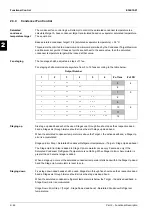
Staging sequence
This section defines which compressor is the next one to start or stop. In general, compressors with
fewer starts will normally start first, and compressors with more run hours will normally stop first.
Compressor staging sequence can also be determined by an operator defined sequence via set
points.
■
Next To Start
The next compressor to start must meet the following requirements:
Lowest sequence number of those compressors available to start:
■
If sequence numbers are equal, it must have the least starts.
■
If starts are equal, it must have least run hours.
■
If run hours are equal, it must be the lowest numbered compressor.
■
Next To Stop
The next compressor to shut down must meet the following requirements:
Lowest sequence number of the compressors that are running:
■
If sequence numbers are equal, it must have the most run hours.
■
If run hours are equal, it must be the lowest numbered compressor.
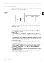
Compressor
capacity control in
cool mode
In Cool mode, evaporator LWT is controlled to within 0.2°C of the target under constant flow conditions
by controlling capacity of the individual compressors.
Compressors are loaded with a fixed step scheme. The rate of capacity adjustment should be
determined by the time between capacity changes. The farther away from the target, the faster
compressors will be loaded or unloaded.
The logic should project ahead to avoid overshoot, such that the overshoot does not cause the unit to
shut off due to evaporator LWT dropping below the target minus the Shutdown Delta T set point while
there is still a load on the loop at least equal to the minimum unit capacity.
Capacity of the compressors should be controlled so that when possible their capacities are balanced.
Circuits that are running in manual capacity control or running with active capacity limiting events
should not be considered in the capacity control logic.
The compressor capacities should be adjusted one at a time while maintaining a capacity imbalance
that does not exceed 12.5%.
Содержание EWAD620-C17C-SL
Страница 2: ......
Страница 8: ...ESIE10 01 1 2 Part 1 System Outline 3 1 1 5 ...
Страница 111: ...ESIE10 01 General Outline Part 1 System Outline 1 105 3 1 4 5 1 36 1 Power Compressor 1 2 ...
Страница 112: ...General Outline ESIE10 01 1 106 Part 1 System Outline 3 1 1 4 5 1 36 2 Power Compressor 3 ...
Страница 113: ...ESIE10 01 General Outline Part 1 System Outline 1 107 3 1 4 5 1 36 3 Kit Pumps ...
Страница 114: ...General Outline ESIE10 01 1 108 Part 1 System Outline 3 1 1 4 5 1 36 4 Circuit Fan Power Supply 1 ...
Страница 115: ...ESIE10 01 General Outline Part 1 System Outline 1 109 3 1 4 5 1 36 5 Circuit Fan Power Supply 1 ...
Страница 116: ...General Outline ESIE10 01 1 110 Part 1 System Outline 3 1 1 4 5 1 36 6 Circuit Fan Power Supply 2 ...
Страница 117: ...ESIE10 01 General Outline Part 1 System Outline 1 111 3 1 4 5 1 36 7 Circuit Fan Power Supply 2 ...
Страница 118: ...General Outline ESIE10 01 1 112 Part 1 System Outline 3 1 1 4 5 1 36 8 Circuit Fan Power Supply 3 ...
Страница 119: ...ESIE10 01 General Outline Part 1 System Outline 1 113 3 1 4 5 1 36 9 Circuit Fan Power Supply 3 ...
Страница 120: ...General Outline ESIE10 01 1 114 Part 1 System Outline 3 1 1 4 5 1 36 10 Unit Control Circuit Power Supply ...
Страница 121: ...ESIE10 01 General Outline Part 1 System Outline 1 115 3 1 4 5 1 36 11 Analog Inputs Output Board ...
Страница 122: ...General Outline ESIE10 01 1 116 Part 1 System Outline 3 1 1 4 5 1 36 12 Digital Inputs Board ...
Страница 123: ...ESIE10 01 General Outline Part 1 System Outline 1 117 3 1 4 5 1 36 13 Digital Outputs Board ...
Страница 124: ...General Outline ESIE10 01 1 118 Part 1 System Outline 3 1 1 4 5 1 36 14 Digital Outputs Board ...
Страница 125: ...ESIE10 01 General Outline Part 1 System Outline 1 119 3 1 4 5 1 36 15 Extension Control Fans 1 2 ...
Страница 126: ...General Outline ESIE10 01 1 120 Part 1 System Outline 3 1 1 4 5 1 36 16 Extension Control Fans 3 ...
Страница 127: ...ESIE10 01 General Outline Part 1 System Outline 1 121 3 1 4 5 1 36 17 Extension Control Fans 4 ...
Страница 128: ...General Outline ESIE10 01 1 122 Part 1 System Outline 3 1 1 4 5 1 36 18 Expansion Input Output Unit Alarm Limiting ...
Страница 129: ...ESIE10 01 General Outline Part 1 System Outline 1 123 3 1 4 5 1 36 19 Expansion Control Compressor 1 ...
Страница 130: ...General Outline ESIE10 01 1 124 Part 1 System Outline 3 1 1 4 5 1 36 20 Expansion Control Compressor 1 ...
Страница 131: ...ESIE10 01 General Outline Part 1 System Outline 1 125 3 1 4 5 1 36 21 EEXV Compressor 1 ...
Страница 132: ...General Outline ESIE10 01 1 126 Part 1 System Outline 3 1 1 4 5 1 36 22 Expansion Control Compressor 2 ...
Страница 133: ...ESIE10 01 General Outline Part 1 System Outline 1 127 3 1 4 5 1 36 23 Expansion Control Compressor 2 ...
Страница 134: ...General Outline ESIE10 01 1 128 Part 1 System Outline 3 1 1 4 5 1 36 24 EEXV Compressor 2 ...
Страница 135: ...ESIE10 01 General Outline Part 1 System Outline 1 129 3 1 4 5 1 36 25 Expansion Control Compressor 3 ...
Страница 136: ...General Outline ESIE10 01 1 130 Part 1 System Outline 3 1 1 4 5 1 36 26 Expansion Control Compressor 3 ...
Страница 137: ...ESIE10 01 General Outline Part 1 System Outline 1 131 3 1 4 5 1 36 27 EEXV Compressor 3 ...
Страница 138: ...General Outline ESIE10 01 1 132 Part 1 System Outline 3 1 1 4 5 1 36 28 Pumps Control ...
Страница 139: ...ESIE10 01 General Outline Part 1 System Outline 1 133 3 1 4 5 1 36 29 Terminals M1 M2 ...
Страница 140: ...General Outline ESIE10 01 1 134 Part 1 System Outline 3 1 1 4 5 1 36 30 Terminals M3 ...
Страница 141: ...ESIE10 01 General Outline Part 1 System Outline 1 135 3 1 4 5 1 36 31 Terminals M5 MQ ...
Страница 148: ...General Outline ESIE10 01 1 142 Part 1 System Outline 3 1 1 4 5 ...
Страница 150: ...ESIE10 01 2 2 Part 2 Functional Description 3 1 2 5 ...
Страница 170: ...The Digital Controller ESIE10 01 2 22 Part 2 Functional Description 3 1 2 4 5 ...
Страница 200: ...Functional Control ESIE10 01 2 52 Part 2 Functional Description 3 1 2 4 5 ...
Страница 202: ...ESIE10 01 3 2 Part 3 Troubleshooting 3 1 3 5 ...
Страница 254: ...Alarms and Events ESIE10 01 3 54 Part 3 Troubleshooting 3 1 3 4 5 ...
Страница 266: ...Controller Inputs and Outputs ESIE10 01 3 66 Part 3 Troubleshooting 3 1 3 4 5 ...
Страница 280: ...ESIE10 01 4 2 Part 4 Commissioning and Test Run 3 1 4 5 ...
Страница 286: ...Pre Test Run Checks ESIE10 01 4 8 Part 4 Commissioning and Test Run 3 1 4 5 ...
Страница 289: ...ESIE10 01 Running Data Part 4 Commissioning and Test Run 4 11 3 4 5 1 ...
Страница 290: ...Running Data ESIE10 01 4 12 Part 4 Commissioning and Test Run 3 1 4 5 ...
Страница 292: ...ESIE10 01 5 2 Part 5 Maintenance 3 1 5 ...


