ESIE10-01
Functional Control
Part 2 – Functional Description
2–35
3
2
4
5
1
2.2.9
Unit Capacity Control
Unit capacity control will be performed as described in this section. All unit capacity limits described in
following sections must be applied as described.
Compressor
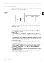
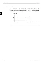
staging in cool
mode
The first compressor on the unit should be started when evaporator LWT is higher than the target plus
the Startup Delta T set point.
An additional compressor should be started when Evaporator LWT is higher than the target plus the
Stage Up Delta T set point.
When multiple compressors are running, one should shut down if evaporator LWT is lower than the
target minus the Stage down Delta T set point.
The last compressor running should shut down when the evaporator LWT is lower than the target
minus the Shut Down Delta T set point.
■
Stage Up Delay
A minimum amount of time should pass between compressors starting, which is defined by the
Stage Up Delay set point. This delay should only apply when at least one compressor is running.
If the first compressor starts and quickly fails on an alarm, another compressor may start without
this minimum time passing.
For units in Ice mode, a fixed stage up delay of one minute between compressor starts should be
used in this mode. When at least one compressor is running, the other compressors should start
as quickly as possible with respect to the stage up delay.
■
Required Load for Stage Up
An additional compressor should not be started until all running compressors are at a capacity
higher than the Load Stage Up set point, or running in a limited state.
■
Light Load Stage Down
When multiple compressors are running, one should shut down if all running compressors are at a
capacity lower than the Load Stage Down set point and the evaporator LWT is less than the target
plus the Stage Up Delta T set point. A minimum amount of time should pass between compres-
sors stopping as a result of this logic, which is defined by the Stage Down Delay set point.
■
Maximum Circuits Running
If the number of compressors running is equal to the Max Circuits Running set point, no additional
compressors should be started.
When multiple compressors are running, one should shut down if the number of compressors run-
ning is more than the Max Circuits Running set point.
Load
Stop Last
Unload
Unload
+ Stop
Load + Start
Start first
Содержание EWAD620-C17C-SL
Страница 2: ......
Страница 8: ...ESIE10 01 1 2 Part 1 System Outline 3 1 1 5 ...
Страница 111: ...ESIE10 01 General Outline Part 1 System Outline 1 105 3 1 4 5 1 36 1 Power Compressor 1 2 ...
Страница 112: ...General Outline ESIE10 01 1 106 Part 1 System Outline 3 1 1 4 5 1 36 2 Power Compressor 3 ...
Страница 113: ...ESIE10 01 General Outline Part 1 System Outline 1 107 3 1 4 5 1 36 3 Kit Pumps ...
Страница 114: ...General Outline ESIE10 01 1 108 Part 1 System Outline 3 1 1 4 5 1 36 4 Circuit Fan Power Supply 1 ...
Страница 115: ...ESIE10 01 General Outline Part 1 System Outline 1 109 3 1 4 5 1 36 5 Circuit Fan Power Supply 1 ...
Страница 116: ...General Outline ESIE10 01 1 110 Part 1 System Outline 3 1 1 4 5 1 36 6 Circuit Fan Power Supply 2 ...
Страница 117: ...ESIE10 01 General Outline Part 1 System Outline 1 111 3 1 4 5 1 36 7 Circuit Fan Power Supply 2 ...
Страница 118: ...General Outline ESIE10 01 1 112 Part 1 System Outline 3 1 1 4 5 1 36 8 Circuit Fan Power Supply 3 ...
Страница 119: ...ESIE10 01 General Outline Part 1 System Outline 1 113 3 1 4 5 1 36 9 Circuit Fan Power Supply 3 ...
Страница 120: ...General Outline ESIE10 01 1 114 Part 1 System Outline 3 1 1 4 5 1 36 10 Unit Control Circuit Power Supply ...
Страница 121: ...ESIE10 01 General Outline Part 1 System Outline 1 115 3 1 4 5 1 36 11 Analog Inputs Output Board ...
Страница 122: ...General Outline ESIE10 01 1 116 Part 1 System Outline 3 1 1 4 5 1 36 12 Digital Inputs Board ...
Страница 123: ...ESIE10 01 General Outline Part 1 System Outline 1 117 3 1 4 5 1 36 13 Digital Outputs Board ...
Страница 124: ...General Outline ESIE10 01 1 118 Part 1 System Outline 3 1 1 4 5 1 36 14 Digital Outputs Board ...
Страница 125: ...ESIE10 01 General Outline Part 1 System Outline 1 119 3 1 4 5 1 36 15 Extension Control Fans 1 2 ...
Страница 126: ...General Outline ESIE10 01 1 120 Part 1 System Outline 3 1 1 4 5 1 36 16 Extension Control Fans 3 ...
Страница 127: ...ESIE10 01 General Outline Part 1 System Outline 1 121 3 1 4 5 1 36 17 Extension Control Fans 4 ...
Страница 128: ...General Outline ESIE10 01 1 122 Part 1 System Outline 3 1 1 4 5 1 36 18 Expansion Input Output Unit Alarm Limiting ...
Страница 129: ...ESIE10 01 General Outline Part 1 System Outline 1 123 3 1 4 5 1 36 19 Expansion Control Compressor 1 ...
Страница 130: ...General Outline ESIE10 01 1 124 Part 1 System Outline 3 1 1 4 5 1 36 20 Expansion Control Compressor 1 ...
Страница 131: ...ESIE10 01 General Outline Part 1 System Outline 1 125 3 1 4 5 1 36 21 EEXV Compressor 1 ...
Страница 132: ...General Outline ESIE10 01 1 126 Part 1 System Outline 3 1 1 4 5 1 36 22 Expansion Control Compressor 2 ...
Страница 133: ...ESIE10 01 General Outline Part 1 System Outline 1 127 3 1 4 5 1 36 23 Expansion Control Compressor 2 ...
Страница 134: ...General Outline ESIE10 01 1 128 Part 1 System Outline 3 1 1 4 5 1 36 24 EEXV Compressor 2 ...
Страница 135: ...ESIE10 01 General Outline Part 1 System Outline 1 129 3 1 4 5 1 36 25 Expansion Control Compressor 3 ...
Страница 136: ...General Outline ESIE10 01 1 130 Part 1 System Outline 3 1 1 4 5 1 36 26 Expansion Control Compressor 3 ...
Страница 137: ...ESIE10 01 General Outline Part 1 System Outline 1 131 3 1 4 5 1 36 27 EEXV Compressor 3 ...
Страница 138: ...General Outline ESIE10 01 1 132 Part 1 System Outline 3 1 1 4 5 1 36 28 Pumps Control ...
Страница 139: ...ESIE10 01 General Outline Part 1 System Outline 1 133 3 1 4 5 1 36 29 Terminals M1 M2 ...
Страница 140: ...General Outline ESIE10 01 1 134 Part 1 System Outline 3 1 1 4 5 1 36 30 Terminals M3 ...
Страница 141: ...ESIE10 01 General Outline Part 1 System Outline 1 135 3 1 4 5 1 36 31 Terminals M5 MQ ...
Страница 148: ...General Outline ESIE10 01 1 142 Part 1 System Outline 3 1 1 4 5 ...
Страница 150: ...ESIE10 01 2 2 Part 2 Functional Description 3 1 2 5 ...
Страница 170: ...The Digital Controller ESIE10 01 2 22 Part 2 Functional Description 3 1 2 4 5 ...
Страница 200: ...Functional Control ESIE10 01 2 52 Part 2 Functional Description 3 1 2 4 5 ...
Страница 202: ...ESIE10 01 3 2 Part 3 Troubleshooting 3 1 3 5 ...
Страница 254: ...Alarms and Events ESIE10 01 3 54 Part 3 Troubleshooting 3 1 3 4 5 ...
Страница 266: ...Controller Inputs and Outputs ESIE10 01 3 66 Part 3 Troubleshooting 3 1 3 4 5 ...
Страница 280: ...ESIE10 01 4 2 Part 4 Commissioning and Test Run 3 1 4 5 ...
Страница 286: ...Pre Test Run Checks ESIE10 01 4 8 Part 4 Commissioning and Test Run 3 1 4 5 ...
Страница 289: ...ESIE10 01 Running Data Part 4 Commissioning and Test Run 4 11 3 4 5 1 ...
Страница 290: ...Running Data ESIE10 01 4 12 Part 4 Commissioning and Test Run 3 1 4 5 ...
Страница 292: ...ESIE10 01 5 2 Part 5 Maintenance 3 1 5 ...


