ESIE10-01
General Outline
1–97
3
1
4
5
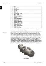
Note:
Water inlet and outlet are indicative. Please refer to the machine dimensional diagrams for exact
water connection of the partial recovery exchangers.
Description of the
refrigeration cycle
with partial heat
recovery
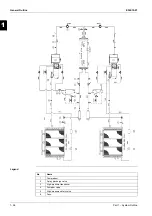
The low-temperature refrigerant gas from the evaporator is drawn by the compressor through the
electric motor, cooling it. It is subsequently compressed and during this process, the refrigerant mixes
with the oil from the oil separator.
The high-pressure oil-refrigerant mix is drawn into the high-efficiency oil separator, that separates it.
The oil depositing on the bottom of the separator through pressure difference is sent back to the
compressor while the refrigerant that has been separate from the oil is sent to the partial recovery
exchanger, where it dissipates the heat from post-overheating cooling, warming the water which
travels through the exchanger. On leaving the exchanger, the refrigerant fluid enters the condensation
bank where, by forced ventilation, it is condensed.
The condensed fluid at saturation temperature passes through the subcooling section where it loses
even more heat, increasing cycle efficiency.
The subcooled fluid then passes through the high-efficiency filter dryer. It subsequently passes
through the lamination element, which, by means of a pressure drop, starts the evaporation process.
The result at this point is a low-pressure and low-temperature liquid-gas mixture entering the
evaporator.
When the refrigerant liquid-vapour is uniformly distributed in the direct expansion evaporator tubes,
heat is exchanged with the cooling water, thus reducing the temperature, changing state until complete
evaporation, followed by superheating.
Once it has reached the superheated-vapour state, the refrigerant leaves the evaporator and is once
again taken into the compressor to repeat the cycle.
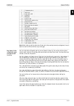
7
Condensation bank
8
Load valve
9
2-way angle valve
10
Filter dryer
11
Sight glass
12
Solenoid valve
13
Thermostatic expansion valve
14
Non-return valve
15
Electronic expansion valve
16
Water outlet temp. transducer
17
Evaporator
18
Water inlet temp. transducer
19
Low-pressure safety valve
20
Suction valve (optional)
21
Suction gas temp. transducer
22
Suction gas press. transducer
23
High-pressure pressure switch
24
Oil/delivery press. transd.
25
Delivery gas temp. transducer
26
Liquid injection valve
27
Liquid injection mesh filter
Содержание EWAD620-C17C-SL
Страница 2: ......
Страница 8: ...ESIE10 01 1 2 Part 1 System Outline 3 1 1 5 ...
Страница 111: ...ESIE10 01 General Outline Part 1 System Outline 1 105 3 1 4 5 1 36 1 Power Compressor 1 2 ...
Страница 112: ...General Outline ESIE10 01 1 106 Part 1 System Outline 3 1 1 4 5 1 36 2 Power Compressor 3 ...
Страница 113: ...ESIE10 01 General Outline Part 1 System Outline 1 107 3 1 4 5 1 36 3 Kit Pumps ...
Страница 114: ...General Outline ESIE10 01 1 108 Part 1 System Outline 3 1 1 4 5 1 36 4 Circuit Fan Power Supply 1 ...
Страница 115: ...ESIE10 01 General Outline Part 1 System Outline 1 109 3 1 4 5 1 36 5 Circuit Fan Power Supply 1 ...
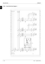
Страница 116: ...General Outline ESIE10 01 1 110 Part 1 System Outline 3 1 1 4 5 1 36 6 Circuit Fan Power Supply 2 ...
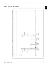
Страница 117: ...ESIE10 01 General Outline Part 1 System Outline 1 111 3 1 4 5 1 36 7 Circuit Fan Power Supply 2 ...
Страница 118: ...General Outline ESIE10 01 1 112 Part 1 System Outline 3 1 1 4 5 1 36 8 Circuit Fan Power Supply 3 ...
Страница 119: ...ESIE10 01 General Outline Part 1 System Outline 1 113 3 1 4 5 1 36 9 Circuit Fan Power Supply 3 ...
Страница 120: ...General Outline ESIE10 01 1 114 Part 1 System Outline 3 1 1 4 5 1 36 10 Unit Control Circuit Power Supply ...
Страница 121: ...ESIE10 01 General Outline Part 1 System Outline 1 115 3 1 4 5 1 36 11 Analog Inputs Output Board ...
Страница 122: ...General Outline ESIE10 01 1 116 Part 1 System Outline 3 1 1 4 5 1 36 12 Digital Inputs Board ...
Страница 123: ...ESIE10 01 General Outline Part 1 System Outline 1 117 3 1 4 5 1 36 13 Digital Outputs Board ...
Страница 124: ...General Outline ESIE10 01 1 118 Part 1 System Outline 3 1 1 4 5 1 36 14 Digital Outputs Board ...
Страница 125: ...ESIE10 01 General Outline Part 1 System Outline 1 119 3 1 4 5 1 36 15 Extension Control Fans 1 2 ...
Страница 126: ...General Outline ESIE10 01 1 120 Part 1 System Outline 3 1 1 4 5 1 36 16 Extension Control Fans 3 ...
Страница 127: ...ESIE10 01 General Outline Part 1 System Outline 1 121 3 1 4 5 1 36 17 Extension Control Fans 4 ...
Страница 128: ...General Outline ESIE10 01 1 122 Part 1 System Outline 3 1 1 4 5 1 36 18 Expansion Input Output Unit Alarm Limiting ...
Страница 129: ...ESIE10 01 General Outline Part 1 System Outline 1 123 3 1 4 5 1 36 19 Expansion Control Compressor 1 ...
Страница 130: ...General Outline ESIE10 01 1 124 Part 1 System Outline 3 1 1 4 5 1 36 20 Expansion Control Compressor 1 ...
Страница 131: ...ESIE10 01 General Outline Part 1 System Outline 1 125 3 1 4 5 1 36 21 EEXV Compressor 1 ...
Страница 132: ...General Outline ESIE10 01 1 126 Part 1 System Outline 3 1 1 4 5 1 36 22 Expansion Control Compressor 2 ...
Страница 133: ...ESIE10 01 General Outline Part 1 System Outline 1 127 3 1 4 5 1 36 23 Expansion Control Compressor 2 ...
Страница 134: ...General Outline ESIE10 01 1 128 Part 1 System Outline 3 1 1 4 5 1 36 24 EEXV Compressor 2 ...
Страница 135: ...ESIE10 01 General Outline Part 1 System Outline 1 129 3 1 4 5 1 36 25 Expansion Control Compressor 3 ...
Страница 136: ...General Outline ESIE10 01 1 130 Part 1 System Outline 3 1 1 4 5 1 36 26 Expansion Control Compressor 3 ...
Страница 137: ...ESIE10 01 General Outline Part 1 System Outline 1 131 3 1 4 5 1 36 27 EEXV Compressor 3 ...
Страница 138: ...General Outline ESIE10 01 1 132 Part 1 System Outline 3 1 1 4 5 1 36 28 Pumps Control ...
Страница 139: ...ESIE10 01 General Outline Part 1 System Outline 1 133 3 1 4 5 1 36 29 Terminals M1 M2 ...
Страница 140: ...General Outline ESIE10 01 1 134 Part 1 System Outline 3 1 1 4 5 1 36 30 Terminals M3 ...
Страница 141: ...ESIE10 01 General Outline Part 1 System Outline 1 135 3 1 4 5 1 36 31 Terminals M5 MQ ...
Страница 148: ...General Outline ESIE10 01 1 142 Part 1 System Outline 3 1 1 4 5 ...
Страница 150: ...ESIE10 01 2 2 Part 2 Functional Description 3 1 2 5 ...
Страница 170: ...The Digital Controller ESIE10 01 2 22 Part 2 Functional Description 3 1 2 4 5 ...
Страница 200: ...Functional Control ESIE10 01 2 52 Part 2 Functional Description 3 1 2 4 5 ...
Страница 202: ...ESIE10 01 3 2 Part 3 Troubleshooting 3 1 3 5 ...
Страница 254: ...Alarms and Events ESIE10 01 3 54 Part 3 Troubleshooting 3 1 3 4 5 ...
Страница 266: ...Controller Inputs and Outputs ESIE10 01 3 66 Part 3 Troubleshooting 3 1 3 4 5 ...
Страница 280: ...ESIE10 01 4 2 Part 4 Commissioning and Test Run 3 1 4 5 ...
Страница 286: ...Pre Test Run Checks ESIE10 01 4 8 Part 4 Commissioning and Test Run 3 1 4 5 ...
Страница 289: ...ESIE10 01 Running Data Part 4 Commissioning and Test Run 4 11 3 4 5 1 ...
Страница 290: ...Running Data ESIE10 01 4 12 Part 4 Commissioning and Test Run 3 1 4 5 ...
Страница 292: ...ESIE10 01 5 2 Part 5 Maintenance 3 1 5 ...


