36
PIM00504
9.5.1 Digital
inputs
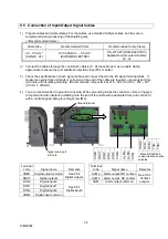
These are sequence input signals that control the operations of this unit from an external device.
Connect them as necessary by following the information below.
Terminal Name
Signal name
Remarks
COM2
Digital input common
Can be either positive or negative
DIN0
Digital input 0
Start/stop signal(factory default on:start/ OFF:stop)
DIN1
Digital input 1
(Reserved) (Do not connect.)
DIN2
Digital input 2
(Reserved) (Do not connect.)
Note: When a stop command has been input via digital input 0, “STP” is displayed on the panel.
Note: Secure a time of at least 1 minute between stopping and starting the unit.
CAUTION
Prepare an external power supply that is DC24 V
±
DC1 V/0.5 A minimum.
It is not possible to supply power from this controller to external destinations.
The current flowing to each input circuit is 5 mA (typ.). If a circuit is configured with contacts,
etc., pay attention to the minimum current for those contacts, etc.
Internal circuit
External power supply
DC24V
DIN0
DIN1
DIN2
COM2
4.7 k
Ω
1 k
Ω
0.1 uF
5 mA


