background image


71 

PIM00504 

13.6  Oil Filler Port Cum Air Breather Maintenance Instructions 

13.6.1 Removal method 

Turn the cap in the counterclockwise direction by hand and remove it. 


13.6.2 Cleaning 

Air blow the filter section to blow off deposits and adhering material.  Also remove dirt from inside the 
strainer’s cylinder. 
 

13.6.3 Mounting 

Fit the cap by turning in the clockwise direction by hand to the position where it stops. 
 

 WARNING 


When using air blow, wear protective glasses to avoid getting deposits and dirt in your eyes. 


Strainer 

Cap

Содержание ECORICH EHU 40 Series

Страница 1: ...1 PIM00504 Hybrid Hydraulic System ECORICH Design 40 Series EHU1404 EHU2504 EHU2507 EHU3007 Instruction Manual DAIKIN INDUSTRIES LTD Oil Hydraulic Division ...

Страница 2: ...y guards removed in order to explain the details When running this product be sure to refit the covers and guards in their original positions as stipulated and follow the instructions in this manual The contents of this manual are subject to modification as appropriate for the sake of improving the product changing specifications or improving the users convenience For the latest version please che...

Страница 3: ...tative Characteristic Diagrams 17 3 4 External Dimensions 18 3 5 Hydraulic Circuit 19 Chapter 4 COMPONENT PARTS AND PART NAMES 20 Chapter 5 PROCEDURE FOR STARTING UP 21 Chapter 6 CHECKS UPON RECEIVING THE PRODUCT 22 6 1 Check on the Contents of the Packaging 22 6 2 Check on the Model 22 Chapter 7 TRANSPORTATION INSTALLATION 23 7 1 Transportation 23 7 1 1 Transportation in the packaged state 23 7 1...

Страница 4: ...rs 53 12 4 2 P39 DO_S Digital output selection P47 RMOT Alarm relay output maintenance notification enable disable 53 12 5 Pressure Switch 54 12 5 1 Parameter list 54 12 5 2 Explanation of parameters 55 12 6 Settings Relating to Warnings Alarms 56 12 6 1 Setting judgment criteria for E64 Dry running error 56 12 6 2 Setting related to E66 Temperature error due to pressure holding rotation speed dro...

Страница 5: ...ance Instructions 72 13 7 1 Removal method 72 13 7 2 Cleaning 72 13 7 3 Reassembly 73 13 8 High pressure Safety Valve Adjustment Instructions 73 13 9 Fixed Throttle φ0 8 Mounting Instructions 75 13 10 Minimum Rotational Speed Adjustment Instructions 76 Chapter 14 Output Signal Timing Charts 77 14 1 Timing Chart at Powering Up 77 Chapter 15 ABOUT Hybrid Win MAINTENANCE CONTROL FUNCTIONS 79 ...

Страница 6: ...structions given in this manual include important information regardless of their categories Be sure to observe all of them 1 2 Notes on Safety 1 2 1 Disclaimers Daikin shall not be responsible for any damage attributable to fire earthquake a third party s action or other accidents or customers intentional acts misuse or use under abnormal conditions Daikin shall not be responsible for any consequ...

Страница 7: ... manual the catalog the delivery specifications and elsewhere Never modify the product Also never disassemble it except for the purposes of inspection as described in this manual Otherwise there is a risk of electric shock fire and injury When this product fails it stops running and cannot maintain the hydraulic pressure supplied To ensure that machines and units do not enter a dangerous state whe...

Страница 8: ...opping and running of the unit by turning the power ON OFF When stopping and running of the unit with start stop signals leave an interval of at least 0 5 seconds between the stop command and restarting 4 This hydraulic unit is equipped with a safety valve The high pressure safety valve is set at 1 5 MPa as factory default Readjust the set pressure of the high pressure safety valve according to yo...

Страница 9: ...k Otherwise there is a risk of electric shock Use an EN60947 2 compliant no fuse breaker and earth leakage circuit breaker with overcurrent protection Otherwise there is a risk of electric shock and fire For the capacities of circuit breakers refer to 9 2 Overall Wiring Diagram Ground the grounding terminals in accordance with the law in the country concerned Otherwise there is a risk of electric ...

Страница 10: ...e there is a risk of failures and shortening of service life 1 5 2 Operation DANGER Do not operate switches with wet hands Otherwise there is a risk of electric shock While the product is powered up do not change the wiring or connect disconnect terminals etc Otherwise there is a risk of electric shock accidents and damage Do not turn on and shut off the power frequently Otherwise there is a risk ...

Страница 11: ... not change the wiring or connect disconnect terminals etc Otherwise there is a risk of electric shock accidents and damage CAUTION Wear protective glasses and gloves while carrying out the work Do not touch the controller board directly Otherwise it could be damaged by static electricity Carry out withstand voltage tests at DC2kV or lower Applying voltages higher than this may cause damage Do not...

Страница 12: ... development by Daikin the energy efficiency of the electric motor section has been increased The Daikin hybrid hydraulic system ECORICH is a friendly system for both people and the environment ECORICH realizes revolutionary energy saving characteristics and low noise by combining advanced hydraulic technology and motor inverter technology ...

Страница 13: ...ions option None Standard none C RS422 485 communication The factory default setting is RS422 communication h Optional function None Standard none i N Non standard unit control number None Standard product 3 digit number or codes for unit options Code combination comprising up to 6 digits of alphabetic characters Code Description F Water fill test tank M Water leak test tank B Oil filler port yell...

Страница 14: ... If there is no unit option the code is terminated at the controller option and the hyphen is deleted Example EHU2504 40 SC 5 Regarding codes for other options or non standard unit control number 1 Codes for other options shall comprise up to six digits of alphabetic characters in ascending sequence with left alignment 2 Non standard unit number shall comprise three numerical digits Examples BFGJK...

Страница 15: ...tput contact capacity DC30 V max 1A ALM NO open when abnormal ALM NC closed when abnormal COM common Communications port RS 485 RS 422 Serial communications port Can be used only with communications option Communications port UART Communications port for service For communications with a personal computer a dedicated USB UART communications converter is required 1 The maximum flow rate is the theo...

Страница 16: ...standard EN60204 1 Turning the power ON OFF within a short time will significantly shorten the life of the controller If operation is to be repeatedly started stopped with an interval of shorter than 8 minutes use start stop signals Note however that they must be used with an interval of at least 0 5 seconds between the stop command and restarting Be sure to ground ground terminals in accordance w...

Страница 17: ...perature of 40 C 2 The above PQ characteristics diagrams show the operating range in terms of actual flow rates 3 Restrict continuous discharge flow rate at the maximum pressure to 5 L min or less Q discharge rate L min Q flow rate L min Q discharge rate L min Q flow rate L min P pressure MPa P pressure MPa P pressure MPa P pressure MPa ...

Страница 18: ...18 PIM00504 3 4 External Dimensions 4 φ13 holes positions 4 φ10 holes positions Oil filling Oil drain port Section at A A Dimensions of mounting holes for installation ...

Страница 19: ...PIM00504 3 5 Hydraulic Circuit Part No Name 1 Oil tank 2 Suction strainer 3 Oil level gauge 4 1 Inverter driven motor pump 4 2 Controller 5 Oil filler port cum air breather 6 Oil cooler Above the oil level ...

Страница 20: ...MPONENT PARTS AND PART NAMES Operation panel Controller Oil cooler DC fan Oil tank Front View of Unit Safety valve Inverter driven motor pump Oil filler port cum air breather Oil level gauge Oil outlet port cum oil drain port ...

Страница 21: ...L RUNNING Be sure to check the following points before turning the power on Is the product installed correctly Has the piping been done correctly Has hydraulic oil been supplied Has the wiring been done correctly Is the power supply voltage correct 6 Flushing operation See Chapter 10 TRIAL RUNNING 7 Replacement with new oil See Chapter 10 TRIAL RUNNING 8 Air bleeding See Chapter 10 TRIAL RUNNING 9...

Страница 22: ... piece Quick instruction manual 1 copy 6 2 Check on the Model CAUTION Check that the model designations indicated on the product nameplates of the motor pump and controller match the ordered product Using a product that is incorrect will result in breakage Check with the product nameplates that the actual item matches the ordered product For details on model designations see 2 2 Model Codes This i...

Страница 23: ...t When transporting the product hoist it by using the holes provided for hooks at two locations Using other locations will lead to a risk of falling toppling over Check the mass of the hydraulic unit and make sure that the hoisting load is within the rated load of the hoisting equipment DANGER Hoisting the product using locations other than the hoisting holes the pump piping etc risks the product ...

Страница 24: ...or air intake exhaust Install the unit at a well ventilated location where heat will not build up and secure a surrounding space of 10 cm from each of the four end faces of the unit Also take care that the temperature of the intake air complies with the stipulated ambient temperature 40 C max WARNING If the intake air exhaust spaces described above are not secured the heat exchange function of the...

Страница 25: ...erioration of the hydraulic oil shortening the service life of the oil 7 2 2 Securing the hydraulic unit Secure the hydraulic unit either on a level platform or level floor that will not be affected by the vibration of the main machine M10 bolts at 4 locations For details on the mounting method and position refer to the Delivery Specification outside drawing WARNING If the hydraulic unit is not se...

Страница 26: ...1 5 MPa DANGER When connecting hoses allow at least the hydraulic hose manufacturer s recommended bend radius Regarding the method for securing the hoses fix them as recommended by the hose manufacturer When doing the piping work make the piping strong enough for the pressures to be used CAUTION Use hoses for the piping to this product Connect the hoses without any twisting In cases where excessiv...

Страница 27: ...while the tank is not full of oil will cause seizure and or wear of the pump leading to breakage During the initial operation of the machine oil is supplied to the hydraulic circuits at the machine side and the oil in the tank may decrease Add oil to bring the height of the oil level to within the stipulated range Depending on the hydraulic circuits at the machine side the fluctuations in oil leve...

Страница 28: ...f a no fuse breaker conforming to European standard EN60947 2 to the source power supply of this product in order to protect the electrical circuits against short circuits overcurrents etc and to prevent electric shock for the capacity for each model see 9 3 Installation of the Breaker Be sure to ground ground terminals in accordance with the law in the country concerned Make a direct connection w...

Страница 29: ...exterior cover needs to be mounted Mount it by following the procedure below Engage the corners of the controller and corners of the cover together and close the cover Holding the grips at the left and right of the cover engage the cover with the bottom of the controller 1 2 Exterior cover Controller box Engage the parts Grips 3 ...

Страница 30: ...terior cover go into the mating parts on the interior cover Check that the 7 segment display is located in the center of the display window in the operating section sheet Tighten the two screws in the lower part of the cover then tighten the two screws at the top Projection Mating part Exterior cover back face Interior cover Vicinity of screws 4 Display Operating section Position check with the di...

Страница 31: ...Input power supply 3 phase 200 200 220 V 50 60 60 Hz Control power supply input 1 phase 200 200 220 V 50 60 60 Hz Only when control power supply option selected Communications port for maintenance Hybrid Win connection point RS422 RS485 communications Only when communications option selected Power supply line ground Digital output or Ready to run Positive common Negative common External power supp...

Страница 32: ...ECTRIC OA W1613 OHM ELECTRIC Applicable cable outer diameter φ11 to φ13 2 Use a ground cable the same size as the power cable or larger 3 Pass the cables through the controller s wiring port to accomplish the wiring work At the wiring port use a cable clamp appropriate to ensure the port satisfies protection class IP54 or better 4 Connect the power cable to the terminal block The screws for connec...

Страница 33: ...rminals provided with this product for connecting the power supply Use an M4 cross recessed pan head screw and washer assembly 8 mm long for the power supply ground terminal Be sure to ground ground terminals in accordance with the law in the country concerned Make a direct connection without going through a circuit breaker Do not connect the power supply cable to the input output signal terminals...

Страница 34: ...d of the cable are required use rod type crimp terminals with insulating cladding Recommended crimp terminal 216 322 0 3 mm2 216 221 0 5 mm2 WAGO 4 You are recommended to ground at one side When grounding inside the controller crimp a ring type crimp terminal with insulating cladding onto the end of the cable with a dedicated tool and connect it with a control signal cable grounding screw M4 Termi...

Страница 35: ... securely connected CAUTION Check the specifications of each signal before making the connections Be sure to terminate shielded cables and connect them to the shielded cable grounding terminal If noise is not eliminated even when connected to the shielded cable grounding terminal make a single point grounding connection on your own equipment disconnect the grounding at the unit Controller interior...

Страница 36: ...igital input 2 Reserved Do not connect Note When a stop command has been input via digital input 0 STP is displayed on the panel Note Secure a time of at least 1 minute between stopping and starting the unit CAUTION Prepare an external power supply that is DC24 V DC1 V 0 5 A minimum It is not possible to supply power from this controller to external destinations The current flowing to each input c...

Страница 37: ...ding on the value of parameter P39 See 12 4 COM1 Digital output common Can be either positive or negative CAUTION Prepare a DC24 V DC1 V 0 5 A power supply externally It is not possible to supply power from this controller to external destinations The maximum output current of the output circuit is 50 mA resistance load Note that driving a load exceeding the permissible current may damage the circ...

Страница 38: ...ム出力コモン 電源ON 正常時 CAUTION The switching capacity of the contact outputs is DC24 V 1 A at resistance load Note that driving a load exceeding the permissible current may damage the contacts or other components The minimum applicable load for the contact outputs is DC24 V 10 mA at resistance load but this is only a guide to the lower limit where switching is possible with a minute load The value varies...

Страница 39: ...l cooler is running C That the pressure indicated on the controller s operation panel display rises after the sound of the pump running 2 Flushing operation When the starting check is completed connect all the piping except for the actuators in a loop then flush for about two hours by passing hydraulic oil through the return filter 3 Changing the hydraulic oil Turn the power off drain all of the h...

Страница 40: ...ng keys DOWN key Used to select monitor data select parameter numbers and set parameter values The UP key increments the value and the DOWN key decrements the value UP key ENT key Used to confirm selections for parameter numbers parameter settings etc 11 2 Functions of the Operation Panel 11 2 1 Function overview The operation panel has the following functions Mode Details Regular mode Displays th...

Страница 41: ...the LEDs flash momentarily Normal In the normal status the current pressure is displayed Stopped Displayed when a stop command is in effect and when the pressure is 0 15 MPa or lower AC failure This is displayed flashing in the event of an AC failure status where the power supply is shut off while charging the unit Occurrence of an alarm warning When an alarm warning occurs the corresponding alarm...

Страница 42: ...is is reserved for the system n10 Motor temperature C Displays the motor temperature n11 Radiating fin temperature C Displays the temperature of the radiating fins n12 Main circuit DC voltage V Displays the direct current voltage of the controller s main circuit The voltage value is the supply power voltage multiplied by the square root of 2 and it varies depending on the running status n13 Reserv...

Страница 43: ...rm code exceeds 999 it is cleared to 0 11 4 2 Monitor mode operations 最大データ番号の 次はn00に戻ります のいずれか 通常モード モニタモード データ番号の選択 値表示 Press the key in the regular mode The mode will switch to the monitor mode Select the data number to be displayed by using the key or key During data number selection the display will flash Confirm the data number by pressing the key The value for the selected data number will ...

Страница 44: ... to be displayed by using the key or key During data number selection the display will flash 3 Confirm the data number by pressing the key The value for the selected data number will be displayed 4 Change the set value by incrementing or decrementing it with the and keys 5 Confirm the set value and return to data number selection by pressing the key Regular mode Holding down together Approx 2 seco...

Страница 45: ... code will be displayed approximately 2 seconds after a set value has been changed 6 Confirm the set value with the key The next data code will be displayed 7 Repeat steps 4 5 and 6 8 Pressing the key will switch the display to the data number selection screen Parameters whose values have been changed up until that time will retain the changed values 9 Setting the flow rate setting qL 0 will switc...

Страница 46: ...y will flash A00 is the latest alarm with older alarm displayed in sequence in this order A01 A02 3 Confirm the alarm history number with the key The corresponding alarm code and the following data upon occurrence of the alarm concerned will be displayed alternately 4 Return to the alarm history number selection by pressing the or key A00 History of alarm numbers 2 Latest alarm Previous alarm 9th ...

Страница 47: ...he alarm 5 A u DC link voltage V DC link voltage at occurrence of the alarm 6 A c Radiating fin temperature 0 1 C Radiating fin temperature at occurrence of the alarm 7 A L Reserved for the system 8 A F Reserved for the system 9 A h Operation time minutes min Operation time at occurrence of the alarm 10 A H Operation time hours h 11 A t Operation time thousands of hours 1000 h represents a numeric...

Страница 48: ...isplayed on the operation panel can be retained It is also possible to record the L63 Pressure switch actuation warning in the alarm history although it is not usually recorded there Value L63 Indication Retention Recording in Alarm History 0 Not retained No recorded 1 Retained No recorded 2 Retained Recorded 12 5 P04 DS_P Pressure unit selection setting 0 MPa indication 1 PSI indication 0 Enables...

Страница 49: ...ed for the system This is reserved for the system P29 C_TM Reserved for the system This is reserved for the system P30 DF_N Reserved for the system This is reserved for the system P31 P_SN Pressure sensor rated value 1 35 MPa 10 Sets the rated pressure of the pressure sensor Normally this setting does not need to be changed P32 S_TM Surgeless start time 0 01 9 99 sec 0 50 Sets the start up time fo...

Страница 50: ... the cooling fan 12 7 1 P46 TVMJ Maintenance implementation review enable disable 0 Maintenance implementation review disabled 1 Maintenance implementation review enabled 0 Selects whether or not to issue an E66 motor temperature rise due to pressure holding speed drop alarm on occurrence of an L67 pressure holding speed drop warning while H52 TVMR Maintenance request is set to 1 12 6 P47 RMOT Ala...

Страница 51: ...9 105 Sets the threshold value for the motor electronic thermal relay overload warning 12 6 3 Flow rate indications are displayed as shown below Flow Rate in the Setting Mode Display Details Edited value 5 rounded up 4 rounded down Maximum value Rounded down Minimum value Truncation 0 1 L min CAUTION The P04 Pressure unit selection setting is set to indication in MPa units as the factory default I...

Страница 52: ...ncies should be accomplished by turning digital input terminal DIN1 ON and OFF Memo When using the product without using the ON OFF digital input signals setting 1 for this parameter causes the hydraulic unit to start automatically in response to powering up 12 3 P13 PL0 QL0 Pressure Flow Rate Characteristics and Settings Set the pressure set value for PL0 and the flow rate set value for QL0 Displ...

Страница 53: ...MOT Alarm relay output maintenance notification enable disable Operation 0 7 8 10 12 0 Open at alarm occurrence or at hydraulic switch actuation 1 Open at alarm occurrence or at hydraulic switch actuation When an E66 alarm occurs ON OFF repeated for 10 minutes 11 0 Open at alarm occurrence or at hydraulic switch actuation 1 Open at alarm occurrence or at hydraulic switch actuation When an E66 alar...

Страница 54: ...vely The pressure switch is set as follows 12 5 1 Parameter list No Code Parameter Name Setting range Default value Unit P01 SW_L Pressure switch actuation level 0 to 35 0 0 Function disabled 0 0 MPa 0 to 507 0 Function disabled 0 0 10 PSI P02 T_SW Pressure switch output delay time 0 00 9 99 0 00 sec P03 PSWH Pressure switch indication retention 0 Disabled 1 Indication retained 2 Display and recor...

Страница 55: ...the indication Pressure drop detection P01 Pressure switch actuation level Sets the actuation value of the pressure switch Setting the value to 0 disables the pressure switch function P02 Pressure switch output delay time This is the delay time between the pressure dropping below P01 Pressure switch actuation level and the pressure drop being confirmed Pressure recovery detection P38 Pressure swit...

Страница 56: ...sabled 1 Maintenance implementation review enabled 0 An E66 Temperature error due to pressure holding rotation speed drop alarm occurs when either of the following two conditions have been satisfied 1 The conditions for occurrence of the E41 alarm Abnormal motor temperature rise have been established while an L67 warning Holding pressure speed drop is in effect 2 When 1 is set for parameter P46 TV...

Страница 57: ...rge pressure For this reason pressure commands and flow rate commands are increased with a fixed gradient to suppress the generation of surge pressure Display Code Parameter Name Setting range Default value Unit P32 S_TM Surgeless start time 0 01 to 9 99 0 5 sec Note that the gradient of the command value can be adjusted with S_TM but that the gradient is subject to restriction internally in the c...

Страница 58: ... pressure for judging a reverse rotation warning the motor start can be delayed beyond the reverse rotation warning judgment wait time end point or the point when the reverse rotation warning is canceled The time charts when a reverse rotation warning has been issued and when none has been issued are presented below Time chart for a start when no reverse rotation warning has been issued Time chart...

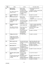
Страница 59: ...r motor pump E12 Overspeed The motor speed has exceeded 120 of the maximum speed Overshoot due to sudden acceleration Adjust the control gain to moderate the acceleration deceleration response Motor control error Same as E10 E15 Insufficient voltage The main circuit voltage has dropped Controller failure Replace the controller Low power supply voltage Check the power supply voltage in the monitor ...

Страница 60: ...t Improve the power supply environment Power supply cable internal harness connection fault disconnection Replace the controller E25 Voltage sensor error There is an error in the voltage detection section and voltage detection is not possible Controller failure Replace the controller E26 Motor control error Motor control fault Set value for the high pressure safety valve is too high Adjust the set...

Страница 61: ... Review the setting of the high pressure safety valve Replace the motor pump The ambient temperature is too high Install the unit at a location where the ambient temperature is within the stipulation Install the unit at a location with good ventilation Controller failure Replace the controller E42 Radiating fin thermistor disconnection The device thermistor is disconnected or short circuited Contr...

Страница 62: ...or wiring and connect it correctly Oil intake takes time Change the values set for parameters P35 Dry running judgment pressure and P36 Dry running judgment time E66 Temperature error due to pressure holding rotation speed drop The throttle is clogged Clean the high pressure safety valve s throttle Adjust the throttle Replace the oil E90 Internal error The software cannot be initialized normally F...

Страница 63: ... communication error After completion of initialization internal communication was discontinued for the stipulated time or longer Controller internal communication error Replace the controller The CPU does not work Communication fault due to noise Controller failure ...

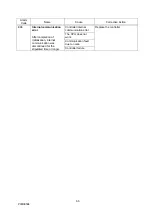
Страница 64: ...ped Replace the fuse for the fan Replace the cooling fan Replace the controller The radiator is clogged Clean or replace the radiator The motor rotation speed has risen Check if the amount of oil leaking from the circuit at the main machine has increased Review the setting of the high pressure safety valve Replace the motor pump The ambient temperature is too high Install the unit at a location wh...

Страница 65: ...or replace the cooling fan L63 Pressure switch actuation The pressure switch has been actuated The pressure reached the value set for parameter P01 Pressure switch or lower If there is nothing abnormal in the operation of the main machine review the set value for the pressure switch or the delay time L67 Holding pressure rotation speed drop When target rotational speed 300 min 1 and the status whe...

Страница 66: ...If the hydraulic oil color changes toward brown and reaches ASTM level L4 bright yellow replace it For the specifications of the hydraulic oil refer to 3 1 2 Conditions of Use Motor cooling fan Motor unit Once a month Once a month Check that the motor cooling fan is rotating and check for dust accumulation Accumulation of a large amount of dust will lessen the cooling effect so it should be cleane...

Страница 67: ...inutes after turning the power supply to the controller OFF before working on terminals A capacitor with a large capacity is used inside the controller and working while the capacitor is charged poses a risk of electric shock and other hazards Always wait at least 5 minutes the time required to discharge the electric charge in the capacitor before starting work involving touching or disconnecting ...

Страница 68: ... into contact with rotating parts When touching the interior of the controller abide by the following procedure to prevent electric shocks i Shut off the source power supply to the hydraulic unit Set the power supply circuit breaker of the circuit that is supplying the power to OFF Hang a tag stating for example Operation Prohibited Work in Progress on the power supply circuit breaker or other dev...

Страница 69: ...f the DC fan during the work Note that oil will flow out from the piping and oil cooler during disassembly 13 5 1 Removing the oil cooler 1 Disconnect the connector for the DC fan wiring 2 Remove the hose clamps 2 locations and pull off the two hoses fitted to the oil cooler At this time fit e g a blind plug to the hoses before starting further work since oil may leak due to reverse flow of oil fr...

Страница 70: ...erior of the core 13 5 4 Cleaning the DC fan Using e g a rag clean not just the fan blades and casing but also the clearance between the fan blades and casing CAUTION Never steam blow or air blow because foreign material will get inside the motor 13 5 5 Reassembly After completing the cleaning reassemble to the original state After completion of reassembly check that the unit runs normally by foll...

Страница 71: ...e it 13 6 2 Cleaning Air blow the filter section to blow off deposits and adhering material Also remove dirt from inside the strainer s cylinder 13 6 3 Mounting Fit the cap by turning in the clockwise direction by hand to the position where it stops WARNING When using air blow wear protective glasses to avoid getting deposits and dirt in your eyes Strainer Cap ...

Страница 72: ...ur hexagonal bolts M8 20L securing the top plate and tank and hoist the motor by its suspension plates to separate it from the tank 3 This will reveal the suction strainer loosen it with e g an adjustable wrench and remove it 13 7 2 Cleaning Air blow the filter section to blow off deposits and adhering material Also remove dirt from inside the strainer s cylinder Hexagon head bolts M8 20L four Suc...

Страница 73: ...ansition to the main machine s hydraulic circuit blockage due to a stop of a hydraulic actuator for example the set pressure of the safety valve drops and it actuates even in the normal status due to repeated operation over a protracted period or contaminants in the hydraulic oil Judgment method When the oil temperature rise has become faster in comparison with how it was previously When in the pr...

Страница 74: ...n05 motor rotation speed indication in the monitor mode by panel key operation to display the current motor rotation speed 5 Adjust the pressure adjusting screw length in the longitudinal direction and find the actuation start point shown in the figure below 6 Turn the pressure adjusting screw clockwise three fourths of a turn from the actuation start point 7 Tighten the lock nut to complete the a...

Страница 75: ... throttle φ0 8 provided as an accessory Check that there is no residual pressure before mounting it 1 Remove the hexagon socket head T plug Rc 1 4 2 Mount the fixed throttle NPTF1 16 φ0 8 3 Wrap sealing tape around the hexagon socket head T plug Rc 1 4 and fit it as it was A A Section A A Fixed throttle φ0 8 NPTF1 16 NPTF1 16 Hexagon socket head tapered plug Rc 1 4 Hexagon socket head tapered plug...

Страница 76: ...ve for minimum rotational speed adjustment 4 Adjust the throttle valve while monitoring the actual motor rotation speed displayed The motor rotation speed decreases during clockwise rotation and increases during counterclockwise rotation 5 Tighten the lock nut to complete the adjustment 6 Press the mode key to switch to actual pressure indication CAUTION If the minimum rotational speed adjustment ...

Страница 77: ...er supply as shown below When sharing control power supply Judge the charging completed not completed status based on the alarm output or DOUT READY output An alarm output before charging or after stopping indicates an abnormal status Common power supply source to control and main circuit Command possible OFF Waiting to run Charging ON OFF Max 3 seconds ON Command not possible Power supply 3 phase...

Страница 78: ...g it off indicates an abnormal status Individual power supply source to control and the main circuit Command possible OFF Waiting to run Charging ON OFF Max 3 seconds ON Command impossible Power supply 3 phase 200 V Digital input DIN1 start stop signal Digital output D01 READY output OFF Approx 20 msec Contact output ALM_a Unit operation Display Normal running Actual pressure Command impossible Ac...

Страница 79: ... saving set values makes control easier 3 Reading and saving the alarm history This is useful for speeding up the identification of parts that need maintenance and shortening stoppage times It serves as a guide for determining the replacement of consumable parts based on operating time and maintenance intervals Troubleshooting including the diagnosis of the causes of alarm occurrences and correcti...

Страница 80: ... 6 6349 4475 Fax 81 6 6349 7862 Home Page http www daikinpmc com en Contact http www daikin com contact hydraulic For requirements on Maintenance Repair Operation All World Machinery Supply Inc a member of Daikin Group 6164 All World Way Roscoe IL 61073 U S A Phone 1 815 943 9111 Fax 1 815 943 5370 Home Page http www allworldmachinery com us ...

Отзывы: