background image

Check

SiBE12-908

166

Service Diagnosis

3.8

“Inverter Checker” Check

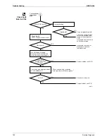
Check No.14

1. Characteristics

If abnormal stop occurs due to compressor startup failure or overcurrent output when using 
inverter unit, it is difficult to judge it results from the compressor failure or other failure (control 
PCB, power transistor, etc.). The inverter analyzer makes it possible to judge the cause of 
trouble easily and securely. (Connect this analyzer as a quasi compressor instead of 
compressor and check the output of inverter)

2. Operation Method

1) Be sure to turn the power off.
2) Install the Inverter Analyzer instead of a compressor.
Note: Make sure the charged voltage of the built-in smoothing electrolytic capacitor drops to 10 
VDC or below before carrying out the service work.

Reference
If the connector terminal of compressor is not a faston terminal (difficult to remove the wire on 
the terminal), it is possible to connect a wire available on site to the unit from output side of 
PCB. (Do not connect it to the compressor at the same time, otherwise it may result in incorrect 
detection.)

„

How to activate inverter test mode

1) Turn the power on.
2) Press the 3 buttons (TEMP

, TEMP

, MODE) on the remote controller simultaneously.

3) Press TEMP

 or 

 button and select 

T

4) Press the MODE button to enter the trial operation mode.
5) Press the MODE button and select FAN mode.
6) Press the ON/OFF button to start inverter test.

(1) Remove the faston terminals

from the terminal block of
the compressor.

(2) Connect the faston terminals

to the terminals of the Inverter
Analyzer.

Inverter Analyzer

Be careful not to touch the terminals
(U,V,W)each other. Otherwise, high voltage is  
applied.

Compressor

(R5160)

Содержание CTXU25G2V1B

Страница 1: ...e current as of January 2009 but subject to change without notice SiBE12 908 Printed in Japan 01 2009 B AK SiBE12 908 Applied Models Inverter Multi Heat Pump Service Manual Inverter Multi System with...

Страница 2: ...SiBE12 908 Table of Contents i Inverter Multi System with Humidifying G Series zHeat Pump Indoor Unit CTXU25G2V1B CTXU35G2V1B CTXU42G2V1B CTXU50G2V1B Outdoor Unit 2MXU40GV1B 2MXU50GV1B...

Страница 3: ...SiBE12 908 ii Table of Contents...

Страница 4: ...13 Other Functions 21 1 14 Table for Special Modes 23 2 Function of Thermistor 25 2 1 Heat Pump Model 25 3 Control Specification 27 3 1 Mode Hierarchy 27 3 2 Automatic switching for HUMID HEAT operat...

Страница 5: ...of Inverter The following drawing shows a schematic view of the inverter principle Phase Description 1 The supplied AC power source is converted into the DC power source for the present 2 The DC power...

Страница 6: ...room temperature variation Energy saving heating and cooling Once the set temperature is reached the energy saving operation enables to maintain the room temperature at low power Frequency Limits The...

Страница 7: ...ature difference is above the zone C after being in the zone A The system resumes from defrost control in any zones except A The operation turns on in any zones except A The monitoring time has passed...

Страница 8: ...to 30 C 2 Main unit setting temperature equals remote controller setting temperature 3 Mode switching point are as follows Heating Cooling switching point Room temperature Main unit setting temperatu...

Страница 9: ...room temperature at startup and the temperature set by the microcomputer is divided into two zones Then the unit operates in the dry mode with an appropriate capacity for each zone to maintain the tem...

Страница 10: ...wing The following table explains the auto swing process for heating cooling dry and fan 3 D Airflow Alternative repetition of vertical and horizontal swing motions enables uniform air conditioning of...

Страница 11: ...oling The fan keeps rotating at the set tap Heating The fan stops Dry The fan will stop after keeps rotating for a few minutes at LL tap Automatic Airflow Control for Heating On heating mode the indoo...

Страница 12: ...umidification apart from other company s methods which just absorb moisture in the indoor air The room is uniformly humidified Humidifier heating operation by air conditioner Moisture gathers around t...

Страница 13: ...ing operation starts the relative humidity in the room lowers temporarily This phenomenon is caused by the increase of the saturation water vapor Therefore the humidity raises gradually after the temp...

Страница 14: ...tive humidity is lowered even if the moisture content is the same e g The rise in the room temperature from 15 C to 25 C will result in the fall in humidity from 40 RH to about 22 RH As humidifying op...

Страница 15: ...tically stops Remark When a room is spacious such as loft style or partitioned by accordion style curtain the ventilation volume is large and may not sometimes reach the set humidity Humidifying time...

Страница 16: ...t 20 Performance compensation by hose length The max piping length is 15 m but the longer the length of the humidifying hose becomes the less the humidifying performance becomes Applicable hose Hose d...

Страница 17: ...or unit The air supply filter is placed at the humidifying hose outlet of the indoor unit side The air supply filter removes about 97 pollen and dust 3 Controlling temperature The fresh air passed thr...

Страница 18: ...cated in the outdoor unit Energy saving system due to low heat loss The room temperature changes little because no wind enters Operation noise is heard because the ventilation fan is located in the ro...

Страница 19: ...indoor unit carries out a sampling every 20 msec and if it detects 10 cycles of the wave in one second in total corresponding to 20msec 10 200msec and when the ON signal continues 3 sec it judges huma...

Страница 20: ...airflow direction to area B left side 2 Detection signal ON in area A Shift the airflow direction to area B left side 3 Detection signal ON in area B Shift the airflow direction to area A right side...

Страница 21: ...of 20 minutes Ex POWERFUL operation in cooling mode Operation mode Fan speed Remote controller set temperature COOL H tap 50 rpm 18 C DRY Dry rotating speed 50 rpm Normally targeted temperature in dry...

Страница 22: ...the ECONO button When this function is ON the maximum capacity is also down Approx 20 This function can only be set when the unit is running Pressing the operation stop button causes the settings to b...

Страница 23: ...GHT SET circuit continues heating or cooling the room at the set temperature for the first one hour then automatically raises the temperature setting slightly in the case of cooling or lowers it sligh...

Страница 24: ...total Those 3 items of ON OFF temperature and time can be set Refer to WEEKLY TIMER Operation on page 86 for detail 1 13 3 Hot Start Function In order to prevent the cold air blast that normally comes...

Страница 25: ...Air Purifying Filter This filter combines the Air Purifying Filter and Titanium Apatite Photocatalytic Deodorizing Filter in a single highly effective unit The filter traps microscopic particles decom...

Страница 26: ...sis mode Left for 60 sec Left for 60 sec CANCEL 5 sec 1 Service check mode 5C T Mode selection view Select with TEMP or button CANCEL 5 sec Left for 60 sec Diagnosis MODE 5 sec MODE Left for 30 min Tr...

Страница 27: ...Refer to the installation manual on page 56 for detail 5 Drying mode Hose Dry operation is a forced drying operation for humidifying hose The operation continues for approx 30 minutes Cooling heating...

Страница 28: ...t exchanger temperature the discharge pipe thermistor is judged as disconnected 3 The outdoor heat exchanger thermistor is used for high pressure protection during cooling operation B Discharge Pipe T...

Страница 29: ...r then the operation halts 5 During heating the indoor heat exchanger thermistors are used for detecting disconnection of the discharge pipe thermistor When the discharge pipe temperature become lower...

Страница 30: ...ion mode In this multi system when both 2 indoor units are operating one of them may enter the standby mode by the following conditions The units in the 2 rooms are different in operation mode The ind...

Страница 31: ...indoor unit will go into humidifying operation while the indoor unit starting operation subsequently Unit 2 will go into standby mode 2 When the humidity of the Unit 1 reaches a target level the unit...

Страница 32: ...thermistor temperature 1 2 Limiting defrost control time 1 3 Forced cooling 1 4 Indoor frequency command 2 Determine upper limit frequency Set a minimum value as an upper limit frequency among the fre...

Страница 33: ...e more than a certain fixed time adjust the frequency up and down according to the D value obtaining the fixed D value When the D value is small lower the frequency When the D value is large increase...

Страница 34: ...the heating is stopped the delay switch of the four way valve must be carried out after the operation stopped Detail The OFF delay of four way valve Energize the coil for 150 sec after unit operation...

Страница 35: ...mpressor Protection Function When turning the compressor from OFF to ON the upper limit of frequency must be set as follows The function must not be used when defrosting 40 class 50 class FCG 1 62 55...

Страница 36: ...mpressor operation stops If a drooping current is continues for 1 0 second after rushing on the drooping zone the frequency will be 2 Hz drooping Repeating the above drooping continues until the curre...

Страница 37: ...the signals being sent from the indoor unit allow the operating frequency limitation and prevent abnormal high pressure The signal from the indoor unit must be divided as follows Detail Conditions for...

Страница 38: ...Operation When the outdoor air temperature is higher than 37 C the fan tap must be set to H When the outdoor air temperature is 18 37 C the fan tap must be set to M When the outdoor air temperature i...

Страница 39: ...after the compressor is started and more than 30 minutes of accumulated fine pass since the start of the operation or ending the defrosting Conditions for Canceling Defrost The judgment must be made...

Страница 40: ...tribution Control 1 Gas pipe isothermal control Liquid pipe temperature control with all ports connected and all rooms being air conditioned 2 SC control Open Control 1 Electronic expansion valve cont...

Страница 41: ...ng room is changed Control of target discharge pipe temperature Defrost control FD 1 Pressure equalizing control Open control when starting Continue Pressure equalizing control Gas pipe isothermal con...

Страница 42: ...changer of the rooms and compensate the electronic expansion valve opening so that the SC of each room becomes the target SC When the actual SC is target SC open the electronic expansion valve of the...

Страница 43: ...electronic expansion valve according to the shift 3 12 9 High Temperature of the Discharge Pipe When the compressor is operating if the discharge pipe temperature exceeds a certain value open the ele...

Страница 44: ...nterrupted too 3 13 3 Insufficient Gas Control Outline If a power consumption is below the specified value in which the frequency is higher than the specified frequency it must be regarded as gas insu...

Страница 45: ...ne Forced operating mode includes only forced cooling Detail Forced Cooling Item Forced Cooling Forced operation allowing conditions 1 The indoor unit is not abnormal but the indoor unit which is not...

Страница 46: ...Control 43 3 15 Additional Function 3 15 1 POWERFUL Operation Mode Compressor operating frequency and outdoor unit airflow rate are increased 3 15 2 Voltage Detection Function Power supply voltage is...

Страница 47: ...Control Specification SiBE12 908 44 Function and Control...

Страница 48: ...Manual 71 3 1 Names of Parts 71 3 2 AUTO DRY COOL HEAT FAN Operation 73 3 3 Adjusting the Airflow Direction 75 3 4 HUMID HEAT Operation 77 3 5 FRESH AIR SUPPLY VENTILATION 79 3 6 COMFORT AIRFLOW and...

Страница 49: ...both sides A Mounting plate A Mounting plate Screws Field supply M4 25L Screws field supply M3 20L Titanium apatite photocatalytic air purifying filter B C Filter frame Air filter Tab Air filters Lef...

Страница 50: ...e mar k of the front grille there are 3 upper hooks Lightly pull the front grille toward you with one hand and push down on the hooks with the fingers of your other hand When there is no work space be...

Страница 51: ...onnector and pull the harness out through the notched part in the figure 3 Replace the electrical wiring cover as it was and pull the harness around as shown in the figure Removal methods of metal pla...

Страница 52: ...5 Check that the flaring is properly made WARNING 1 Do not use mineral oil on flared part 2 Prevent mineral oil from getting into the system as this would reduce the lifetime of the units 3 Never use...

Страница 53: ...Choose heat insulation materials that will withstand this temperature 2 Be sure to insulate both the gas and liquid piping and to provide insulation dimensions as below 3 Use separate thermal insulati...

Страница 54: ...caulking material to prevent water leakage 1 Bore a feed through hole of 70mm in the wall so it has a down slope toward the outside 2 Insert a wall pipe into the hole 3 Insert a wall cover into wall p...

Страница 55: ...inside the wall block the ends of the humidifying hose with tape or the like to prevent water or anything else from entering it until it is connected to the indoor unit and outdoor unit ducts Do not b...

Страница 56: ...hose Insulation tape Piping bundle diagram Cut out the piping through hole Install with a downward slope Cut out the piping through hole Right back piping Right bottom piping Right side piping Humidi...

Страница 57: ...hooks Secure indoor unit to the mounting plate with screws M4 12L 5 3 Wall embedded piping Follow the instructions given under 1 Insert the drain hose to this depth so it won t be pulled out of the d...

Страница 58: ...ers and pour some water into the drain pan to check the water flows smoothly 3 When drain hose requires extension obtain an extension hose commercially available Be sure to thermally insulate the indo...

Страница 59: ...nd emitted Be sure to check the sound If the sound is not heard press MODE button again 4 Pressing TEMP button changes the humidifying hose length You may set the hose length to 6 levels Hold MODE but...

Страница 60: ...breaker is opened again 2 Test items When the bubble sound is heard water may be in the humidifying hose Do the HOSE DRY operation Test items Symptom diagnostic display on RC Check Indoor and outdoor...

Страница 61: ...ifying hoses respectively in upward direction in ROOM A and in downward direction in ROOM B Hole pitch of foot bolts 574 Hole pitch of foot bolts 311 Clamping material Insulation tube Stop valve cover...

Страница 62: ...dation drawing in fix the unit securely by means of the foundation bolts Prepare four sets of M8 or M10 foundation bolts nuts and washers each which are available on the market It is best to screw in...

Страница 63: ...gerant piping the better the performance Connect so that the piping is as short as possible Shortest allow able length per room is 3m Piping to each indoor unit ROOM A B 15m max Total length of piping...

Страница 64: ...inner surface of the flare Use refrigeration oil for R410A 3 Use torque wrenches when tightening the flare nuts to prevent damage to the flare nuts and gas leakage Align the centres of both flares an...

Страница 65: ...es on the gauge manifold and stop the vacuum pump Leave as is for 4 5 minutes and make sure the coupling meter needle does not go back If it does go back this may indicate the presence of moisture or...

Страница 66: ...stop valve is fully closed the refrigerant may slowly leak out do not leave the flare nut removed for a long period of time 2 Do not overfill with refrigerant This will break the compressor Filling a...

Страница 67: ...Prevent mineral oil from getting into the system as this would reduce the lifetime of the units 3 Never use piping which has been used for previous installations Only use parts which are delivered wit...

Страница 68: ...the outside temperature is 10 C or lower 1 2 Using the wireless remote controller 1 Select cooling operation and press the ON OFF button The unit will start 2 Press the TEMP button 2 locations and the...

Страница 69: ...ing hoses exceeds 10m Mark the cuff on the indoor unit side so that the overall length of the hoses after adjustment will be clearly known CAUTION Connect the humidifying hose according to the install...

Страница 70: ...the figure 3 Tighten the screw and secure the humidifying hose cover and outdoor unit 1 Cut out the knockout hole on the humidifying hose cover 2 Insert the humidifying hose 2m into the knockout hole...

Страница 71: ...ting the connection wires to the terminal board using a single core wire be sure to perform curling Problems with the work may cause heat and fires 3 Pull the wire and make sure that it does not disco...

Страница 72: ...ge the humidifying hoses on the outdoor unit for rooms A and B A TTENTION 1 Have the customer actually operate the unit while looking at the manual included with the indoor unit Instruct the customer...

Страница 73: ...a clever method of using it In order to meet this expectation of the users giving sufficient explanations taking enough time can be said to reduce about 80 of the requests for servicing However good t...

Страница 74: ...age 29 13 Indoor Unit ON OFF switch page 8 Push this switch once to start operation Push once again to stop it The operation mode refers to the following table This switch is useful when the remote co...

Страница 75: ...6 TEMPERATURE adjustment buttons It changes the temperature setting 7 MODE selector button It selects the operation mode AUTO DRY COOL HEAT FAN page 8 8 POWERFUL QUIET button POWERFUL and OUTDOOR UNI...

Страница 76: ...OFF button again disappear from the LCD Then OPERATION lamp goes off To change the temperature setting 4 Press TEMPERATURE adjustment button The displayed items on the LCD will change whenever either...

Страница 77: ...the heating capacity In that case the system switches into defrosting operation to take away the frost During defrosting operation hot air does not flow out of indoor unit A pinging sound may be heard...

Страница 78: ...e flaps will begin to swing 2 When the flaps have reached the desired position press SWING button once more The flaps will stop moving disappears from the LCD To adjust the louvers vertical blades 3 P...

Страница 79: ...the figure 3 Dimensional 3 D airflow Using 3 dimensional airflow circulates cold air which tends to collected at the bottom of the room and hot air which tends to collect near the ceiling throughout...

Страница 80: ...om out of two is in HUMID HEAT operation the indoor unit in the other room will go into humidification stand by mode regardless of the selection of the HUMID HEAT operation function for the other room...

Страница 81: ...into a standby state Yellow When the humidity of Room A satisfies the preset condition HUMID HEAT operation in Room A will be switched to the unit in Room B automatically The result is shown in the i...

Страница 82: ...o the room The operation noise is slightly louder When the outdoor temperature is higher than room temperature the airflow rate of FRESH AIR SUPPLY VENTILATION will be low 1 2 Select First selected pr...

Страница 83: ...tion downward while heating page 16 INTELLIGENT EYE The sensors will detect the movement of people in the sensing areas and the louvers will adjust the airflow direction to an area where people are no...

Страница 84: ...vers are controlled and the indoor unit will not direct the airflow towards the people Sensor detection sensitivity changes according to indoor unit location the speed of passersby temperature range e...

Страница 85: ...on in AUTO COOL HEAT or HUMID HEATING mode Note on POWERFUL operation POWERFUL operation cannot be used together with ECONO QUIET or COMFORT operation Priority is given to the function of whichever bu...

Страница 86: ...connecting outdoor unit NOTE ECONO operation can only be set when the unit is running Pressing the OFF button causes the setting to be canceled and the disappears from the LCD ECONO operation is a fu...

Страница 87: ...tton changes the setting rapidly 3 Press OFF TIMER button again and setting time are displayed on the LCD The TIMER lamp lights up To cancel the OFF TIMER operation 4 Press CANCEL button and setting t...

Страница 88: ...button changes the setting rapidly 3 Press ON TIMER button again and setting time are displayed on the LCD The TIMER lamp lights up To cancel ON TIMER operation 4 Press CANCEL button and setting time...

Страница 89: ...can be set in the WEEKLY TIMER The effective use of the copy mode ensures ease of making reservations The use of ON ON ON ON settings for example makes it possible to schedule operating mode and set t...

Страница 90: ...ess SELECT button to select the desired mode Pressing the SELECT button changes or setting in sequence In case the reservation has already been set selecting blank deletes the reservation Go to STEP 9...

Страница 91: ...d for another day of the week Refer to page 24 NOTE Notes on WEEKLY TIMER operation Do not forget to set the time on the remote controller first The day of the week ON OFF TIMER mode time and set temp...

Страница 92: ...ion will be copied to the selected day of the week To continue copying the settings to other days of the week repeat STEP 4 and STEP 5 6 Press PROGRAM button to complete the setting Exit copy mode is...

Страница 93: ...servation deactivated with WEEKLY button is activated once again the last reservation mode will be used To delete reservations Refer to page 22 When selecting desired mode at STEP 4 in setting mode se...

Страница 94: ...h 2 rooms are set to HUMID HEAT operation 1 Priority will be given to the indoor unit in the first selected room and the indoor unit will go into humidifying operation while the indoor unit in the sec...

Страница 95: ...Operation Manual SiBE12 908 92 Installation Operation Manual...

Страница 96: ...t 122 2 14 Incomplete Setting for Hose Length 123 2 15 Freeze up Protection in Other Rooms Unspecified Voltage between Indoor and Outdoor Units 124 2 16 Outdoor Unit PCB Abnormality 125 2 17 OL Activa...

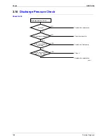
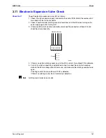
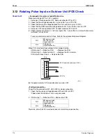
Страница 97: ...Fan System Check DC Motor 163 3 5 Power Supply Waveform Check 164 3 6 Main Circuit Electrolytic Capacitor Check 164 3 7 Refrigerant System Check 165 3 8 Inverter Checker Check 166 3 9 Power Transistor...

Страница 98: ...door unit flashes when any of the following failure is detected 1 When a protection device of the indoor or outdoor unit is activated or when the thermistor malfunctions and the machine does not work...

Страница 99: ...LED indication on the outdoor unit PCB 1 The outdoor unit has 2 green LED LED A LED5 on the PCB The flashing green LED indicates in order condition The turned ON or OFF LED indicates the failure relat...

Страница 100: ...de indication changes in the sequence shown below and notifies with a long beep Note 1 A short beep and two consecutive beeps indicate non corresponding codes 2 To cancel the code display hold the tim...

Страница 101: ...ain from the start when the figure does not blink 4 Press TEMP or button and change the figure until you hear the sound of beep or pi pi 5 Diagnose by the sound pi The figure of the ten s place does n...

Страница 102: ...he ten s place accords with the error code but the one s not beep The both figures of the ten s and one s place accord with the error code See 7 9 Determine the error code The digits indicated when yo...

Страница 103: ...2 H0 Compressor sensor system abnormality 134 H1 Humidifying unit Damper abnormality 135 H6 Outdoor Position sensor abnormality 136 H8 DC voltage DC current sensor abnormality 138 H9 Outdoor air therm...

Страница 104: ...shooting Service Diagnosis 101 UA UH System Freeze up protection in other rooms Unspecified voltage between indoor and outdoor units 124 Lights out of microcomputer status lamp 160 Code Unit Descripti...

Страница 105: ...ower supply is OFF Improper power supply voltage Improper connection of wire Incorrect combination of indoor unit and outdoor unit Battery shortage of remote controller Invalid address setting Protect...

Страница 106: ...r for the power supply breaker ON Caution Be sure to turn off power switch before connect or disconnect connector or parts damage may be occurred Do the other electric appliances work Is the supply vo...

Страница 107: ...Go to LED diagnosis investigate the symptoms R9421 YES NO NO YES Operation lamp flashes Is an error code displayed on the remote controller NO Does it operate on test operation mode YES Diagnose the...

Страница 108: ...g Method of Malfunction Detection Malfunction Decision Conditions Supposed Causes Incorrect temperature setting Incorrect combination of indoor unit and outdoor unit Blocked air filter Insufficient po...

Страница 109: ...model or add another machine Piping length is to be within the specified range Replace the thermistor Change power supply installation Check detailed operating conditions diagnosis by gas pressure op...

Страница 110: ...n Malfunction Decision Conditions Supposed Causes Insufficient capacity of safety breaker Earth leakage breaker is too sensitive Not exclusive circuit The supply voltage is not within rated voltage 10...

Страница 111: ...fill the refrigerant of specified volume Is the capacity of safety breaker as specified R9432 Caution Be sure to turn off power switch before connect or disconnect connector or parts damage may be occ...

Страница 112: ...using saddles and inserting a cushion material Correct them Correct by hand or install piping weight Apply sound insulation sheets of putty Conduct vacuum drying fill the refrigerant of specified vol...

Страница 113: ...hod of Malfunction Detection Malfunction Decision Conditions Supposed Causes Hose length is not set Incorrect hose length setting Short circuited at outdoor unit Blocked humidification filter Insuffic...

Страница 114: ...e occurred Does the set hose length match with the each field hose length Is the humidification filter blocked Blocked NO It does not match YES YES NO It matches Not blocked YES NO Any breakage or blo...

Страница 115: ...tting Explain to the user Explain to the user Set the air outlet at the height of 1 8 m Confirm the humidification performance Low High Not low NO Is the set temperature by remote controller too high...

Страница 116: ...ero cross detection in approximately 10 continuous seconds Supposed Causes Faulty indoor unit PCB Faulty connector connection Troubleshooting Note Connector Nos vary depending on models Connector conn...

Страница 117: ...o the temperature detected by the indoor unit heat exchanger thermistor Malfunction Decision Conditions High pressure control During heating operations the temperature detected by the indoor heat exch...

Страница 118: ...r disconnect connector or parts damage may be occurred Provide sufficient air passage Clean the air filter Clean the heat exchanger Replace the indoor unit PCB Replace the thermistor replace the indoo...

Страница 119: ...ction Decision Conditions When the detected rotation speed does not reach the demanded rotation speed of the target tap and is less than 50 of the maximum fan motor rotation speed Supposed Causes Oper...

Страница 120: ...witch before connect or disconnect connector or parts damage may be occurred Replace fan motor Replace the indoor unit PCB Replace the indoor unit PCB Note The motor may break when the motor connector...

Страница 121: ...an 120 ohms or below about 50 C more than 1 860 kohms Note The values vary slightly in some models Supposed Causes Faulty connector connection Faulty thermistor Faulty PCB Troubleshooting Check No 02...

Страница 122: ...0 04 V or less Supposed Causes Improper connector connection Defective indoor control PCB Defective humidity sensor PCB Troubleshooting Reconnect properly Replace the indoor unit PCB Is it OK R9422 C...

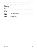
Страница 123: ...for problem Malfunction Decision Conditions When the data sent from the outdoor unit can not be received without error or when the disable status of signal transmission continues for 15 sec Supposed C...

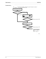
Страница 124: ...may be occurred Check the relay wire between the indoor unit and the outdoor unit for color and number Check outdoor unit LED A Is there any improper wiring YES Poor insulation Is the insulation betwe...

Страница 125: ...connected to outdoor intake model Supposed Causes Connected to wrong model Mounted improper indoor unit PCB Defective indoor unit PCB Mounted improper outdoor unit PCB or defective PCB Troubleshooting...

Страница 126: ...the outdoor unit PCBs are replaced simultaneously the set value is erased Troubleshooting How to check the preset hose length Set the hose length with the remote controller To other UA fault diagnosi...

Страница 127: ...s Operation halt due to unspecified voltage between indoor and outdoor units Supposed Causes Operation halt due to the freeze up protection in other rooms Wrong connections at the indoor unit PCB wron...

Страница 128: ...er Zero cross signal can not be detected Supposed Causes Out of control of microcomputer caused by external factors z Noise z Momentary fall of voltage z Momentary power loss Defective outdoor unit PC...

Страница 129: ...eshooting Check No 02 Refer to P 162 Check No 12 Refer to P 165 Check No 17 Refer to P 169 Check No 31 Refer to P 172 R9438 Caution Be sure to turn off power switch before connect or disconnect connec...

Страница 130: ...P 166 Inverter checker Part No 1225477 Rectify the power supply or replace the outdoor unit PCB Replace the compressor Check the electronic expansion valve Replace the electronic expansion valve Repl...

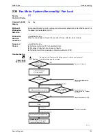
Страница 131: ...ult Supposed Causes Failure in fan motor Disconnection or improper connection of harness connector between fan motor and PCB The fan does not rotate because it gets caught in foreign matter Troublesho...

Страница 132: ...Malfunction Decision Conditions When or more of CT input continues for 2 5 sec The compressor stops if the error occurs and restarts automatically after 3 minutes standby Supposed Causes Overcurrent d...

Страница 133: ...disconnect U V and W harnesses Is there any LED turned off Check No 16 Discharge pressure check Check No 03 Installation condition check Turn off the power supply replace the harnesses and restart the...

Страница 134: ...other error does not occur during the following 60 minute compressor running time total time Supposed Causes Insufficient gas Faulty operation of four way valve Defective discharge pipe thermistor Def...

Страница 135: ...s executed according to the temperature detected by the heat exchanger thermistor Malfunction Decision Conditions Activated when the temperature being sensed by the heat exchanger thermistor rises abo...

Страница 136: ...stop valve Replace the main body or coil of the electronic expansion valve Replace the outdoor unit PCB Replace the outdoor heat exchanger thermistor Replace the outdoor unit PCB R9852 Check installat...

Страница 137: ...ault condition is identified by DC current which is detected before compressor startup Malfunction Decision Conditions When the DC voltage is 50 V or less Supposed Causes Defective PCB Harness disconn...

Страница 138: ...Faulty damper operation due to foreign material Limit switch fault including improper connection Defective motor for damper Troubleshooting OK Check intake air and humidification unit for direct suck...

Страница 139: ...sition detector Malfunction Decision Conditions When the compressor does not run for 15 sec after receiving operation start command The machine shuts down if the fault occurs 16 times Clear condition...

Страница 140: ...e the outdoor unit PCB Replace the compressor Judge Is there any LED turned off R9445 Check No 16 Discharge pressure check NO Caution Be sure to turn off power switch before connect or disconnect conn...

Страница 141: ...When the compressor operation frequency is more than 56 Hz 40 class or 40 Hz 50 class and when the input current is less than 0 25 A Input current is below 0 5 A The machine shuts down when the fault...

Страница 142: ...cision Conditions When power is supplied and the thermistor input is 4 98 V or more or when the thermistor input is 0 02 V or less for 5 sec continuously For J3 Discharge pipe thermistor heat exchange...

Страница 143: ...utdoor air thermistor YES Reconnect properly Replace the thermistor Replace the thermistor Replace the outdoor unit PCB Does the remote controller display the error code again Is it OK R9446 Caution B...

Страница 144: ...fin detected by the fin thermistor with the compressor off Malfunction Decision Conditions With the compressor off the radiation fin temperature is above 80 C The error is cleared when the temperature...

Страница 145: ...r parts damage may be occurred Does the thermistor meet the specification chart of thermistor NO Check No 02 Thermistor resistance check Turn off the power and turn it on again YES NO NO Check the rad...

Страница 146: ...s when the radiation fin temperature is 86 C or more Fault condition is cleared when the radiation fin temperature is below 72 C Shut down when the error repeats 255 times Clear condition Continuous o...

Страница 147: ...switch before connect or disconnect connector or parts damage may be occurred Does the thermistor meet the specification chart of thermistor NO Check No 02 Thermistor resistance check Turn off the po...

Страница 148: ...e compressor is running The machine shuts down when the signal of output overcurrent is sent 8 times from the output overcurrent detection circuit to the microcomputer Clear condition The machine cont...

Страница 149: ...supply again after turning it off Repeated NO YES NO YES NO Turn off the power supply and disconnect U V and W harnesses Turn off the power supply replace the harnesses and restart the compressor afte...

Страница 150: ...nue for 7 minutes Input current input voltage 2111 256 output frequency 361 W Output frequency 51 Hz 50 class The following conditions continue for 7 minutes Input current input voltage 4628 256 outpu...

Страница 151: ...ure outdoor air indoor or outdoor heat exchanger thermistor Replace the compressor Procedure complete Procedure complete R9450 Caution Be sure to turn off power switch before connect or disconnect con...

Страница 152: ...min without fault Supposed Causes Abnormal supply voltage momentary power failure Defective overcurrent detector or defective DC voltage detection circuit Failure in PAM controlled parts Short circui...

Страница 153: ...nditions 1 When the programme of the microcomputer is in bad running order 2 When indoor outdoor unit signal transmission can not be performed for more than 15 sec 3 When zero cross signal can not be...

Страница 154: ...may be occurred Check supply voltage Check indoor unit also because a comunication circuit fault may be caused by the problem related to the indoor unit Rated voltage NO NO Firmly connected NO NO Che...

Страница 155: ...on Replace outdoor unit PCB Reconnect relay wire Replace indoor unit PCB R9453 Disturbance YES NO Grounded YES YES Turn off the power supply Disconnect No 3 terminal and turn on the power supply again...

Страница 156: ...etween microcomputer mounted on the main body and inverter Malfunction Decision Conditions When the data sent from the microcomputer of the inverter can not be received successively for 9 sec the mach...

Страница 157: ...failure of the outdoor unit PCB Monitor in long term R9454 Caution Be sure to turn off power switch before connect or disconnect connector or parts damage may be occurred Is the fault repeated NO NO 0...

Страница 158: ...ose connector Detection fault of fan speed due to defective outdoor unit PCB Troubleshooting Check No 23 Refer to P 170 R9455 Caution Be sure to turn off power switch before connect or disconnect conn...

Страница 159: ...ter the heater turned on Malfunction Decision Conditions When the temperature detected by the thermistor is lower than the outdoor temperature at heater turned off 5 C and this condition continues for...

Страница 160: ...etails refer to PH troubleshooting Replace indoor control PCB A1P Main relay could be damaged When the main relay MRM10 is damaged heater rotor and dehumidification fan do not run Is the supply voltag...

Страница 161: ...entified as an abnormal heater temperature fault Malfunction Decision Conditions When power is supplied and the thermistor input is 4 92 V or more or 0 06 V or less If the humidification fan outlet te...

Страница 162: ...f humidification thermistor within normal range Check No 02 Thermistor resistance check Is the heater cooled well after the power supply turned off Reconnect properly The humidification thermistor is...

Страница 163: ...power supplied For the machine with stand by power save function first set the ON timer using remote controller to release the stand by power save function Is LED A turned off Is LED 5 turned off YES...

Страница 164: ...pply voltage output pins 4 7 3 Check motor control voltage pins 4 3 4 Check rotation command voltage output pins 4 2 5 Check rotation pulse input pins 4 1 7 6 5 4 3 2 1 Motor power supply voltage Unus...

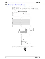
Страница 165: ...each thermistor using tester The relationship between normal temperature and resistance is shown in the graph and the table below For the models in which the thermistor is directly mounted on the PCB...

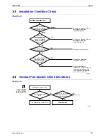
Страница 166: ...the outside air temperature temperature of air taken in by the outdoor unit The outside air temperature shall be 43 C or lower Check the allowable dimensions of the air suction and discharge area Is t...

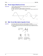
Страница 167: ...3 6 Main Circuit Electrolytic Capacitor Check Check No 11 Do not touch the live parts within 10 min after the breaker is turned off Even after that when you touch the parts check that there is no DC...

Страница 168: ...e the gas R9461 Refrigerant system check blockage gas leakage insufficient gas are to be checked Is the temperature of suction pipe of four way valve extremely high Gas leakage check Refer to the insu...

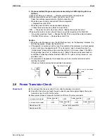
Страница 169: ...carrying out the service work Reference If the connector terminal of compressor is not a faston terminal difficult to remove the wire on the terminal it is possible to connect a wire available on sit...

Страница 170: ...carried out with no load the condition of the compressor is disconnected some of units may stop operation with CT system error due to no electric current or startup failure because the compressor doe...

Страница 171: ...No 16 R9683 NO NO YES YES NO NO YES YES Are the heat exchanger and air filter dirty Is the connection pipe deformed Is the stop valve open Is it high Replace the compressor Open the stop valve Replace...

Страница 172: ...EVs which do not sound clatter disconnect the connectors of these EVs and check them for conductivity 4 If there is no clatter latching sound on all of the EVs in step 2 the outdoor PCB is defective...

Страница 173: ...as follows Refer to the corresponding circuit diagram When FU2 is melted check outdoor fan for proper function If NG in step 2 Defective PCB Replace the PCB If NG in step 4 Defective Hall IC Replace...

Страница 174: ...esistance between pins at both ends of DB1 If the resistance is or less than 1 k the main circuit short terminal of the tester in case of digital terminal terminal of the tester in case of digital ter...

Страница 175: ...resistance at 300 600 NO S80 voltage at DC 130 230 V for 3 sec after compressor starts and then at about DC 12 15V after that Fig 1 Turn off the power and turn it on again Replace the outdoor unit PC...

Отзывы: