background image

14 Configuration

Installer and user reference guide

26

BK+S

Wired remote controller

4P513690-1 – 2018.03

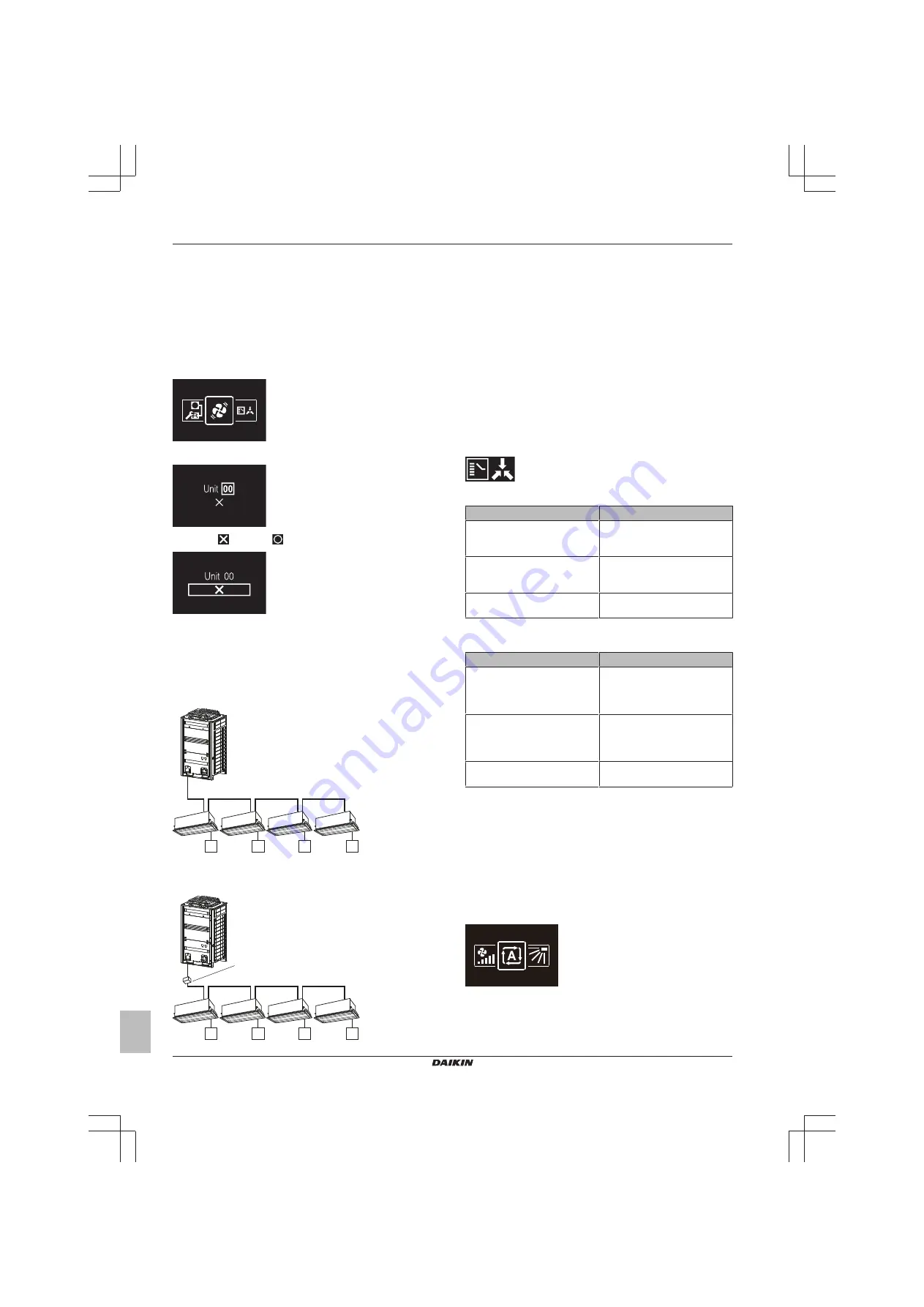
Force fan ON

About Force fan ON

Force  fan  ON  allows  you  to  force  fan  operation  of  individual  indoor
units.  In  this  way,  you  can  check  which  indoor  unit  number  was
assigned to which indoor unit.

To force fan operation

Prerequisite: 

You are in the installer menu.

1

Navigate to the Force Fan ON menu.

2

Select an indoor unit number.

3

Select 

 and press 

 to force fan operation.

Result: 

The  fan  of  the  indoor  unit  that  corresponds  to  the  selected

indoor unit number starts operating.

Switch Cooling/Heating master

About Cooling/Heating masterhood

A

a

b

c

c

c

c

b

b

b

B

a

b

c

c

c

c

b

d

b

b

A

Heat pump system

B

Heat recovery system

a

Outdoor unit

b

Indoor unit

c

Remote controller

d

BS unit

When multiple indoor units are connected to the same outdoor unit,
there  are  restrictions  as  to  the  operation  modes  in  which  they  can
run.  One  outdoor  unit  does  not  allow  for  one  indoor  unit  to  perform
Cooling operation, while another performs Heating operation.

Therefore, the system requires that one indoor unit is set as cooling/
heating master. This indoor unit then decides the operation modes in
which the other (slave) indoor units can run. When one indoor unit is
set  as  cooling/heating  master,  the  other  indoor  units  automatically
become  its  slaves.  For  instructions,  see 

"To  set  Cooling/Heating

masterhood" on page 26

.

Cooling/Heating  masterhood  corresponds  to  the  following  status
icon:

The behaviour of this status icon is according to the following table:

If a controller displays …

Then …

… NO status icon

… The indoor unit connected to
that controller is Cooling/Heating
master.

… a CONSTANT status icon

… The indoor unit connected to
that controller is slave to a
Cooling/Heating master.

… BLINKING status icon

… NO indoor unit is assigned as
Cooling/Heating master yet.

The operation mode behaviour of the indoor units is according to the
following table:

If the master …

Then the slaves …

… is set to "Heating", "Dry", or
"Auto" operation mode

… start running in the same
operation mode as the master.
No other modes are then
available for them.

… is set to "Cooling" operation
mode

... then the slaves cannot run in
"Heating" operation mode, but
can still run in "Cooling", "Fan
only" and "Dry" operation mode.

… is set to "Fan only" mode

… can ONLY run in "Fan only"
mode.

Once  an  indoor  unit  is  set  as  master,  it  can  be  released  from
masterhood.  For  instructions,  see 

"To  release  Cooling/Heating

masterhood" on page 27

.

To set Cooling/Heating masterhood

Prerequisite: 

No  indoor  unit  is  yet  set  as  Cooling/Heating  master

("changeover  under  centralised  control"  icon  blinking  on  all
controllers).

Prerequisite: 

You are operating the controller of the indoor unit that

you want to set as Cooling/Heating master.

1

Navigate to the operation mode menu.

2

Set the operation mode to either Cooling or Heating.

Result: 

The indoor unit is now Cooling/Heating master ("changeover

under centralised control" icon not on controller).

Содержание BRC1H81K

Страница 1: ...Installer and user reference guide Wired remote controller English Installer and user reference guide Wired remote controller BRC1H81W BRC1H81K BRC1H81S ...

Страница 2: ...tem 12 12 1 Master and slave controller 12 12 2 To designate a controller as slave 12 13 Operation 13 13 1 Buttons 13 13 2 Screen 13 13 3 Status indicator 13 13 4 Information 13 13 4 1 Information screen 13 13 4 2 Information menu 14 14 Configuration 14 14 1 Installer menu 14 14 1 1 About the installer menu 14 14 1 2 Screen settings 14 14 1 3 Status indicator settings 15 14 1 4 Field settings 15 1...

Страница 3: ...ay or insecticide near the controller NOTICE To clean the controller do NOT use organic solvents such as paint thinner Possible consequence damage electric shock or fire 1 2 For the installer The precautions described in this document cover very important topics follow them carefully INFORMATION This controller is an option and cannot be used standalone Also see the installation and operation manu...

Страница 4: ...ngineering data A subset of the latest technical data is available on the regional Daikin website publicly accessible The full set of latest technical data is available on the Daikin extranet authentication required For the user 3 Buttons c b d e a a ON OFF When OFF press to turn ON the system As a result the status indicator e will turn ON too When ON press to turn OFF the system As a result the ...

Страница 5: ...ation Indicates that Rotation mode is active Setback Indicates that the indoor unit is operating under setback conditions Icon Description Ventilation Indicates that a heat reclaim ventilation unit is connected INFORMATION For information on the operation mode and ventilation mode icons see 6 1 Operation mode on page 5 and 6 5 1 Ventilation mode on page 8 respectively Most icons are related to thi...

Страница 6: ...ll automatically switch to defrost operation During defrost operation the indoor unit fan will stop operation and the following icon will appear on the home screen The system will resume normal operation after approximately 6 to 8 minutes Hot start VRV only During hot start the indoor unit fan will stop operation and the following icon will appear on the home screen INFORMATION When the system is ...

Страница 7: ...te Result The fields become editable 3 Set the date and time Set with and Confirm with Cycle through the menu until all fields are set correctly Result You set the date and the time INFORMATION Confirming the value in a field will automatically bring you to the next field To finish making settings and leave the menu navigate to and confirm the value in the last field 6 4 Airflow 6 4 1 Airflow dire...

Страница 8: ... the fan speed 1 Navigate to the fan speed menu 2 Use and to adjust the fan speed 3 Press to confirm Result The indoor unit changes its fan speed and the controller returns to the home screen 6 5 Ventilation INFORMATION Ventilation settings can ONLY be made for heat reclaim ventilation units 6 5 1 Ventilation mode The heat reclaim ventilation unit can operate in various operation modes Icon Ventil...

Страница 9: ...doka Assistant app is installed and running Prerequisite Your mobile device supports Bluetooth version 4 2 1 Open the Madoka Assistant app and follow the instructions from there 7 Maintenance and service 7 1 Overview Maintenance and service When the system needs to be maintained or serviced consult your dealer When the following indoor unit components are due for maintenance you will be confronted...

Страница 10: ...y consists of the following stages 1 Determining how you want to route the electrical wiring and nipping away a piece of the rear casing accordingly 2 Mounting the rear casing to the wall 3 Connecting the electrical wiring 4 Closing the controller 11 2 Mounting the controller 11 2 1 About mounting the controller Before you can mount the controller you have to determine the wiring routing and accor...

Страница 11: ...T included NOTICE When wiring run the wiring away from the power supply wiring in order to avoid receiving electric noise external noise INFORMATION P1 and P2 have no polarity 11 3 2 To connect the electrical wiring Connect controller terminals P1 P2 to indoor unit terminals P1 P2 From the top P1P2 From the rear P1P2 From the left P1P2 From the bottom P1P2 11 4 Closing the controller 11 4 1 Precau...

Страница 12: ...oller as slave on page 12 12 1 Master and slave controller a b c d a Outdoor unit b Indoor unit c Master remote controller d Slave remote controller On the information screen master slave status is indicated by the following icons Icon Description Master Slave For more information see 13 4 1 Information screen on page 13 INFORMATION It is only possible to use a master and a slave controller of the...

Страница 13: ... information through status icons Standard Detailed a b c 19 a b c a Messages b Active operation mode c Setpoint temperature Home screen mode is set with remote controller field setting R1 7 Home screen For more information see Remote controller field settings on page 19 Backlight The screen backlight has the following states State Description ON For the controller to be operable the screen backli...

Страница 14: ...r instructions on how to enter the information menu see 14 1 Installer menu on page 14 and Information on page 27 14 Configuration 14 1 Installer menu 14 1 1 About the installer menu In the installer menu you can make the following settings Category Icon Settings Screen settings Brightness Contrast Status indicator settings Intensity Category Icon Settings Field settings Indoor unit field settings...

Страница 15: ...ions on how to make field settings see 14 1 4 Field settings on page 15 For an overview of remote controller field settings see Remote controller field settings on page 19 To set status indicator intensity Prerequisite You are in the installer menu 1 Navigate to the status indicator intensity menu 2 Use and to adjust status indicator brightness 3 Press to confirm Result The status indicator adjust...

Страница 16: ...s you do NOT set the unit number The settings will then apply to all indoor units that are part of that group Second level Setting SW A setting is a settable parameter These are the settings you are making In the field settings tables find the available setting numbers in the SW column Value A value is one of a fixed set of values that you can choose for a setting When the value field contains a t...

Страница 17: ...ing component 3 Use and to change the value of that field setting component 4 Press to confirm that value 5 In the first level select to move to the second level 6 In the second level navigate and select in the same way as you did in the first level 7 Select to confirm and activate made settings SW 00 8 At all times select to go back a level ...

Страница 18: ...sor set the increase decrease increments 1 C 0 5 C 13 23 00 High air outlet velocity set in case of high ceiling applications h 2 7 m 2 7 m h 3 m 3 m h 3 5 m 01 Airflow direction set in case an indoor unit is equipped with an option kit that blocks the airflow 4 way flow 3 way flow 2 way flow 03 Airflow function set whether the indoor unit is equipped with a decoration panel at its air outlet Equi...

Страница 19: ... C 10 2 0 C 11 2 5 C 12 3 0 C 6 7 Home screen 0 Detailed 1 Standard 1 8 Backlight no operation timer 0 5 seconds 1 10 seconds 2 20 seconds 0 9 Status indicator faintness 0 0 OFF 1 1 2 2 3 3 4 5 5 7 6 9 7 11 8 13 9 15 10 17 11 20 9 10 Backlight faintness 0 0 OFF 1 1 2 2 3 3 4 4 5 5 5 11 Status indicator mode 0 Normal 1 Hotel setting 1 2 Hotel setting 2 2 13 Bluetooth Low Energy advertising 0 Always...

Страница 20: ...ellaneous settings Group address and Airnet address DIII Group address To control the system with central control equipment you need to set addresses for Groups Group and or Units Group Unit The Group address and Airnet address menu has two levels You define groups and or units in the first level and set or release addresses for those groups and or units in the second Address Description First lev...

Страница 21: ... settings To RELEASE an address that was previously set change to and then apply settings AirNet address To connect the system to the AirNet monitoring and diagnostics system you need to set AirNet addresses for Indoor units I U Outdoor units O U The Group address and AirNet address menu has two levels You define groups and or units in the first level and set and release an address for those group...

Страница 22: ... controller 4P513690 1 2018 03 Address Description First level Indoor unit I U Define the indoor unit for which you want to set an AirNet address Proceed to the next level Outdoor unit O U Define the outdoor unit for which you want to set an AirNet address Proceed to the next level ...

Страница 23: ...gital input adapter see the installation manual of the digital input adapter In case the digital input adapter does not function properly the external input interlock menu is not available in the installer menu In case a centralised controller is additionally part of the system external input interlock is controlled by the centralised controller The digital input adapter is then overruled To make ...

Страница 24: ... setpoint range and setpoint range limitation 22 C Reset Heat SP Default Reset Setting heating setpoint See indoor unit s setpoint range and setpoint range limitation 22 C INFORMATION When the value for a parameter is this means that when the timers expires nothing changes for that parameter and the current active value is kept Window contact logic Window contact B1 Key card contact B2 Time Action...

Страница 25: ... the previous state When the key card contact is opened while the window contact is open the delay timer will start running When the delay timer expires the reset timer will start running When the reset timer expires the previous state is updated to the Default Reset Setting state Example 1 1 You remove the key card Result The indoor unit continues operating normally until the delay timer expires ...

Страница 26: ... Cooling Heating masterhood on page 26 Cooling Heating masterhood corresponds to the following status icon The behaviour of this status icon is according to the following table If a controller displays Then NO status icon The indoor unit connected to that controller is Cooling Heating master a CONSTANT status icon The indoor unit connected to that controller is slave to a Cooling Heating master BL...

Страница 27: ...g masterhood menu 2 Press to release the indoor unit from its masterhood Result The indoor unit is released from its masterhood Result The controllers of all indoor units display a blinking changeover under centralised control icon Information About the information menu In the information menu you can find the following information Information Description SW1 Controller software ID Ver Controller ...

Страница 28: ... Prerequisite You are close to the controller 1 In the app tap the controller that you want to pair with Result The operating system of your mobile device sends out a pairing request Result The controller displays the following screen 2 In the app accept the pairing request 3 On the controller accept the pairing request by pressing Result The app is paired with the controller INFORMATION Once pair...

Страница 29: ...hange the operation mode Change the setpoint Change the fan speed Change the airflow direction Read out notifications Category Control Configuration and advanced operation Make controller and indoor unit settings General Remote controller firmware update Notifications Remote controller settings Master slave status Screen Status indicator Date and time About Remove bonding information Energy saving...

Страница 30: ...date and time menu you send date and time information to the remote controller from the app You can choose to either send the date and time information of your mobile device Synchronise or to manually create and send date and time information INFORMATION If the controller is disconnected from the power for more than 48 hours the date and the time need to be set again INFORMATION The clock will mai...

Страница 31: ...bility of this function depends on the type of indoor unit 15 5 13 Setpoint range Set a limitation to the temperature setpoint range of both Cooling and Heating operation INFORMATION This function cannot be used when the indoor units are controlled by a centralised controller INFORMATION The default setpoint range limits for both Heating and Cooling operation is 16 C 32 C regardless of whether or ...

Страница 32: ...set a timespan for it INFORMATION To use this function it is required that the indoor units are equipped with a self cleaning decoration panel optional accessory 15 5 20 AirNet address Assign AirNet addresses to the indoor and outdoor units this to connect the system to the AirNet monitoring and diagnostics system First select a unit by way of its unit number then assign it an AirNet address 15 5 ...

Страница 33: ...units can remain inactive during normal operation After a set time i e Rotation cycle time the inactive unit will start operation and a previously active unit will become inactive i e duty rotation Because the units only operate alternately the lifespan of the system increases Backup having a backup unit allows for system redundancy If an active unit goes into error Duty rotation makes sure an ina...

Страница 34: ...behave correspondingly 12 Return to the Test operation menu 13 Tap Stop test operation Result The indoor units leave test operation mode Normal operation is possible again 14 Go to 6 Operation on page 5 and confirm if the indoor unit s behave according to the information set out there 15 Check the error history If required solve the cause of the errors and perform the test operation again INFORMAT...

Страница 35: ...Wipe the screen and other surface parts of the controller with a dry cloth 17 Troubleshooting 17 1 Error codes of the indoor unit When the indoor unit is in error the controller will display on the home screen and confront you with an error screen as soon as you try to enter the main menu Solve the cause of the error and press to remove the error screen For an overview of indoor unit error codes a...

Страница 36: ... is available on the regional Daikin website publicly accessible The full set of latest technical data is available on the Daikin extranet authentication required 18 1 Connection diagram 18 1 1 Typical layout P1 P2 P1 P2 18 1 2 Typical layout for group control 0 1 2 P1 P2 P1 P2 P1 P2 P1 P2 Group control master and slave controller 0 1 2 P1 P2 P1 P2 P1 P2 P1 P2 P1 P2 ...

Страница 37: ...reference guide 37 BRC1H81W K S Wired remote controller 4P513690 1 2018 03 Group control controller digital inputs adapter BRP7A5 0 1 2 P1 P2 P1 P2 P1 P2 P1 P2 P1 P2 18 1 3 Controller DIII central control equipment F1 F2 P1 P2 P1 P2 F1 F2 ...

Страница 38: ......

Страница 39: ......

Страница 40: ...4P513690 1 2018 03 Copyright 2018 Daikin ...

Отзывы: