IM 817-4
Page 55 of 60
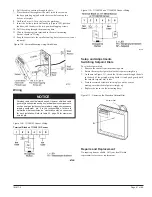
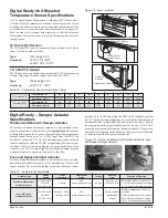
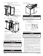
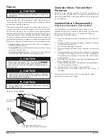
Figure 134 - Oiling Point
Figure 135 - Oiling Point for 1500 cfm units
Unit Ventilator Start-up
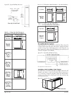
1. Before proceeding inspect the fan system, ensure all parts are
aligned properly and move freely. Inspect fans and fan discharge
area for obstructions. Rotate fan manually. Check that a clean filter
is installed and area in front of unit ventilator is free of debris (see
figure 124). All panels should be in place and properly fastened.
Check for outdoor air leaks and condensation. Ensure the coil section
is properly sealed using the insulating foam donuts supplied.
2. After the unit ventilator has been properly installed, activate unit
electrical power and applicable chilled water/hot water/steam/
refrigerant systems.
3. Using the applicable control, activate the unit ventilator. Depending
on the operating mode selected, the dampers, fans, and other
components should operate as needed.
4. Run the unit ventilator for ten minutes, listening and observing.
Fans should be operating correctly, and rotating in the proper
direction, without unusual noise. Likewise, the unit should be free
of sheet metal rattles and / or unusual noises. All panels should
be in place and properly fastened, and checked for air leaks and
condensation.
End Panel
YC-1934
End of Unit
1/4-20 Tinnerman Nut,
Clip on End Panel
1/4-20 x 1/2 Screw & 1/4 Flat Washer
1/4-20 Tinnerman Nut, Clip
Over Lower Hole in Unit
Corner Angle.
1/4-20 x 1/2 Screw & 1/4 Flat Washer
5"
Access To Fan Shaft Bearing Through Left Top Access Door
Bearing Oiler Cap
Tinnerman Clips
Tinnerman Clips
Screws
(insert through end
panel and thread into
tinnerman clips on unit
subbase)
Screws
(insert through upper mounting holes inside unit end
compartment, and thread into tinnerman clips on end panel)
End Panel w/Cut out
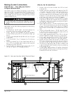
Figure 132 - Install End Panels With Provided Hardware
(1" End Panel Shown)
Figure 133 - Install End Panels With Provided Hardware
(6" End Panel Shown)
NOTICE
Remove debris, dust, dirt, and any obstruction from the area in
front of the return air intake grille at the floor as this will affect
unit performance. If a draftstop system has been installed be
sure that all draftstop intake grilles are unobstructed.
NOTICE
CAUTION
For 1500 cfm units, access to the fan shaft bearing is through
the center front panel. It is located between the third and fourth
fan housing from the right (Figure 135).
NOTICE
1. Position (YC-1934) bracket on wall so angle is 5" from end of unit
and near bottom (see figure 133).
2. Mark and drill required hole for fastening device (not included).
3. Attach bracket to wall.
4. Attach end panel. Bracket should prevent movement of end panel
toward end of unit when pressure is applied to end panel, readjust
bracket if necessary.
Prepare Unit Ventilator(s) for Start-up
Oiling the Fan Shaft End Bearing:
Do not attempt to operate the unit fans until the fan bearings
have been oiled. Oiled bearings provide smooth, and quiet
operation of the fan system.
See Figure 134 for oiling point. Access to fan shaft bearing is through
left top access door (750, 1000, 1250 cfm units only). Lift the oiler
cap. Oil, using a few drops of high grade SAE 20 or 30 nondetergent
oil. Do not over-oil.
G.E. motor manufacturer recommends not oiling the fan motor.
Bearing Oiler Cap

