Page 24 of 60
IM 817-4
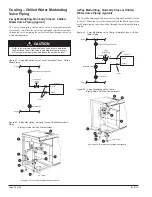
The 2-way EOC CW valve is furnished normally closed to the coil.
When the valve is de-energized (off) there is no flow through the coil.
Energizing the valve allows flow through the coil.
The 3-way EOC CW valve is furnished normally closed to the coil. When
the valve is de-energized (off) the flow bypasses the coil. Energizing
the valve allows flow through the coil.
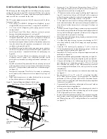
Figure 68 - 2-way EOC, Normally Closed, Chilled Water Valve Piping
Figure 69 - 3-way EOC, Normally Closed, Chilled Water Valve Piping
Return
Return
Balancing and Shutoff Valve
Shutoff Valve
Supply
Supply
2-way EOC
Valve
Unit Coil
Unions
A
B
Return
Return
Supply
Unit Coil
Union
Shutoff Valve
Supply
3-way
EOC Valve
Union
Bypass
A
B
AB
Balancing Valve
Cooling – Chilled Water EOC Valve Piping
Balancing and Shutoff Valve
The 2-way EOC hot water or 2-pipe CW/HW valve is furnished normally
open to the coil. When the valve is de-energized (off) there is full flow
through the coil. Energizing the valve shuts off the water flow.
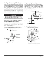
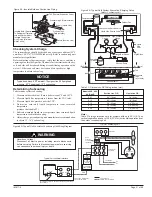
Figure 66 - 2-way EOC, Normally Open, Hot Water or 2-pipe CW/HW
Valve Piping
The 3-way hot water or 2-pipe CW/HW valve is furnished normally
open to the coil. When the valve is de-energized (off) there is full flow
through the coil. Energizing the valve allows the water to bypass the
coil.
Figure 67 - 3-way EOC, Normally Open, Hot Water or 2-pipe CW/HW
Valve Piping
Return
Return
Balancing and Shutoff Valve
Shutoff Valve
Supply
Supply
2-way EOC
Valve
Unit Coil
Unions
A
B
Heating – Hot Water End of Cycle Valve Piping
S5 Sensor
(2-pipe CW/HW Units Only)
Typical Piping Arrangements
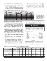
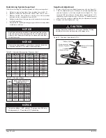
Heating valve actuators should be mounted in an upright position above
the centerline of the valve body and should be piped normally open to
the coil. Modulating valve actuators for hot water applications may be
positioned above the valve body a maximum of 75º from the vertical.
For steam applications only, mount the modulating valve actuator above
the valve body at 45º from the vertical. Two-position, end-of-cycle
(EOC) valves used with face and bypass damper controlled units may
be positioned above the valve body a maximum of 85º from the vertical.
All control valves are shipped loose to help avoid shipping damage
to the piping or the coil connection stub from the weight of the valve,
and to provide the installing contractor with maximum flexibility in
making the field piping connections. Refer to Daikin factory instruction
sheet shipped with the unit for port orientation and a piping schematic.
Control valves must be installed on the units in which they are shipped.
Indiscriminate mixing of valves among units can result in valves not
properly sized for the desired flow rate. Control valves should be
installed so that there is 2" minimum clearance to remove the actuator
from the valve body. As a future service consideration, provide unions
for removal of the unit coil and/or the control valve.
Return
Return
Balancing and Shutoff Valve
Shutoff Valve
Supply
Supply
3-way EOC Valve
Unit Coil
Union
Balancing
Valve
Bypass
A
B
AB
Union
S5 Sensor
(2-pipe CW/HW Units Only)
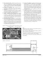
For 2-pipe systems use 3-way End of Cycle Valve (EOC) so supply
water is running through the circuit. The S5 sensor should be mounted
on the supply water pipe.


