Page 32 of 60
IM 817-4
Do not force adjustment stem of TXV. When adjusting superheat
setting, there are a maximum of 10 turns on the stem. Turning
adjustment stem after reaching stop will damage valve.
Table 22 —Saturated Temperature - Pressure Chart
(ºF) R410A-PSIG (ºF) R410A-PSIG (ºF) R410A-PSIG
32
101.1
44
127.7
80
235.8
33
103.2
45
130.2
85
254.7
34
105.2
46
132.6
90
274.5
35
107.4
47
135.1
95
295.5
36
109.5
48
137.5
100
317.6
37
111.7
49
140.1
105
340.9
38
113.9
50
142.6
110
365.4
39
116.2
55
147.0
115
391.2
40
118.4
60
170.1
120
418.3
41
120.7
65
185.2
125
446.9
42
123.0
70
201.1
130
476.8
43
125.4
75
218.0
140
541.4
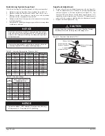
Determining System Superheat
After the subcooling has been determined, check system superheat.
1. Determine required superheat from superheat range, table 23.
2. Measure suction line temperature 6 inches from service valve.
3. Measure suction line pressure at service valve and determine
saturated suction temperature from table 22.
4. Subtract saturated suction temperature from measured temperature
to obtain superheat.
5. Refer to table 23 and adjust charge as required for correct superheat
at ambient conditions.
Each time that charge is added or removed from the system,
allow the system to run approximately 20 - 30 minutes before
pressure and temperature readings are taken and superheat
calculations made.
If system hunting occurs or subcooling is reduced, it may be
necessary to adjust TXV to obtain correct superheat.
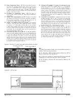
Superheat Adjustment
1.
Remove the seal cap from thermal expansion valve (see figure 91).
2. Turn the adjustment screw clockwise to increase superheat and
counterclockwise to decrease superheat (see figure 91). One
complete 360º turn changes the superheat approximately 3-4ºF,
regardless of the refrigerant type. As much as 30 minutes may be
required for the system to stabilize after the adjustment is made.
3. Replace and hand-tighten seal cap.
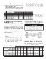
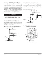
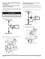
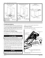
Figure 91 - Superheat Adjustment of TXV
Superheat
Adjustment Screw
Counterclockwise To
Decrease Superheat
Clockwise To Increase
Superheat
Remove Seal Cap
Outdoor
Indoor Coil Air Inlet Temp.
Ambient
DB/WB (50% RH)
75/63
80/67
85/71
105
*
*
8-10
100
*
3-5
9-11
95
*
5-7
11-13
90
*
9-11
13-15
85
5-7
10-12
15-17
80
8-10
12-14
18-20
75
10-12
15-17
21-23
70
13-15
19-21
24-26
65
15-17
21-23
26-28
Table 23 —Superheat Range
Typical conditions - 95ºF ambient, 75 psig suction, 285 psig
head pressure, 6 - 7º superheat, 15ºF subcooling
NOTICE
NOTICE
CAUTION
NOTICE


