197
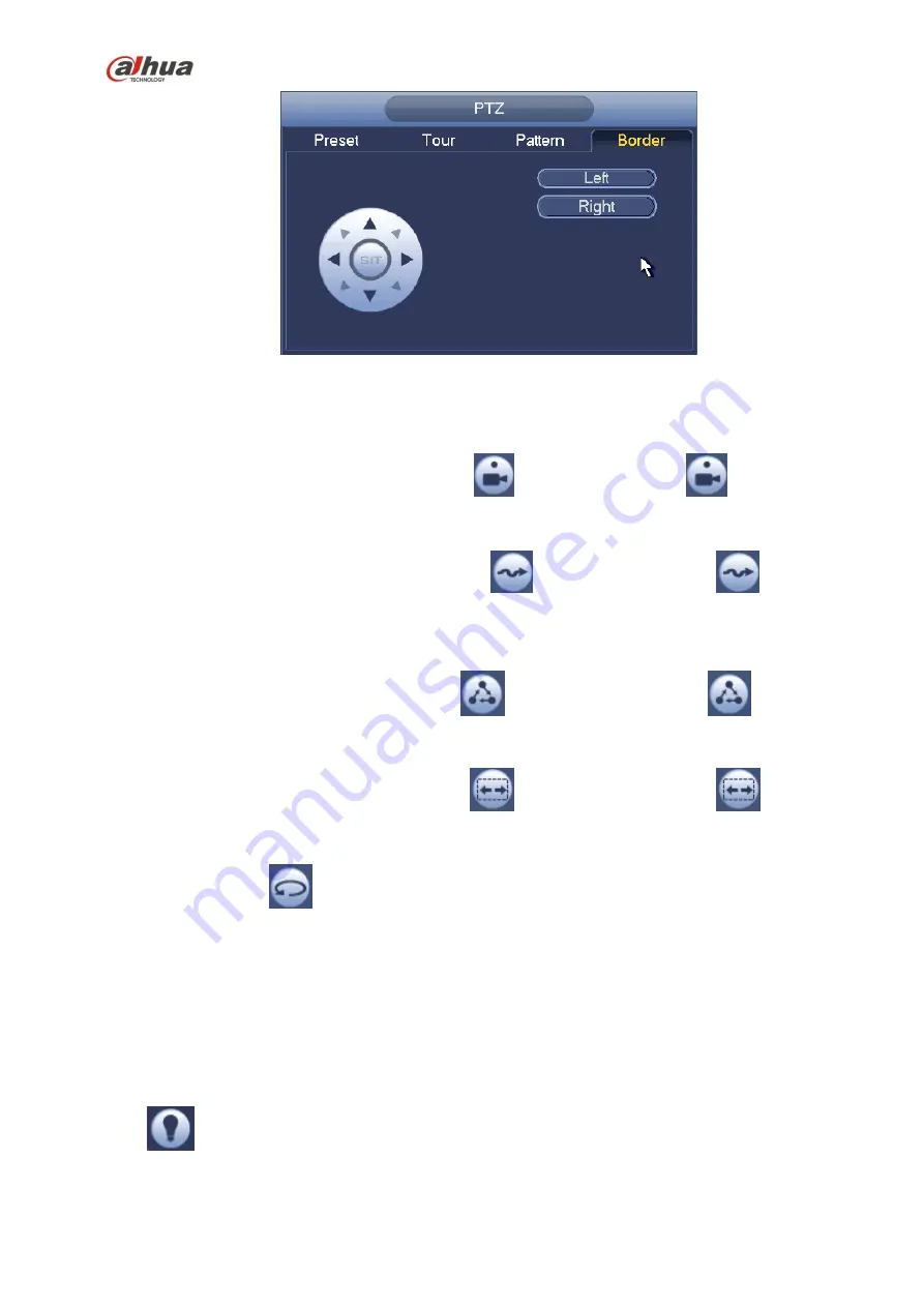
Figure 4-54
4.9.2.2 Call PTZ Function
Call Preset
In Figure 4-49, input preset value and then click
to call a preset. Click
again to stop call.
Call Pattern
In Figure 4-49, input pattern value and then click
to call a pattern. Click
again to stop
call.
Call Tour
In Figure 4-49, input tour value and then click
to call a tour. Click again
to stop call.
Call Scan
In Figure 4-49, input Scan value and then click
to call a tour. Click again
to stop call.
Rotate
In Figure 4-49, click
to enable the camera to rotate.
System supports preset, tour, pattern, scan, rotate, light and etc function.
Note:
Preset, tour and pattern all need the value to be the control parameters. You can define it as y ou
require.
You need to refer to your camera user’s manual for Aux definition. In some cases, it can be used for
special process.
Aux
Click
, system goes to the following interface. The options here are defined by the protocol. The aux
number is corresponding to the aux on-off button of the decoder. See Figure 4-55.
Содержание nvr4208-8p
Страница 1: ...Dahua Network Video Recorder User s Manual V 2 7 0 ...
Страница 159: ...144 Figure 3 3 3 5 4 NVR11HS 41HS W S2 Series Please refer to Figure 3 4 for connection sample ...
Страница 160: ...145 Figure 3 4 3 5 5 NVR41HS W S2 Series Please refer to Figure 3 5 for connection sample ...
Страница 163: ...148 Figure 3 7 3 5 8 NVR42N Series Please refer to Figure 3 8 for connection sample Figure 3 8 ...
Страница 171: ...156 Figure 3 18 3 5 19 NVR78 Series Please refer to Figure 3 19 for connection sample ...
Страница 172: ...157 Figure 3 19 3 5 20 NVR78 16P Series Please refer to Figure 3 20 for connection sample ...
Страница 173: ...158 Figure 3 20 3 5 21 NVR78 RH Series Please refer to Figure 3 21 for connection sample ...
Страница 174: ...159 Figure 3 21 3 5 22 NVR70 Series Please refer to Figure 3 22 for connection sample ...
Страница 175: ...160 Figure 3 22 3 5 23 NVR70 R Series Please refer to Figure 3 23 for connection sample ...
Страница 176: ...161 Figure 3 23 3 5 24 NVR42V 8P Series Please refer to Figure 3 24 for connection sample ...
Страница 177: ...162 Figure 3 24 ...
Страница 188: ...173 Figure 4 19 Click smart add button you can see device enables DHCP function See Figure 4 20 Figure 4 20 ...
Страница 243: ...228 Figure 4 89 Figure 4 90 ...
Страница 244: ...229 Figure 4 91 Figure 4 92 ...
Страница 259: ...244 Figure 4 110 Figure 4 111 ...
Страница 260: ...245 Figure 4 112 Figure 4 113 ...
Страница 261: ...246 Figure 4 114 Figure 4 115 ...
Страница 263: ...248 Figure 4 117 Figure 4 118 ...
Страница 290: ...275 Figure 4 148 In Figure 4 148 click one HDD item the S M A R T interface is shown as in Figure 4 149 Figure 4 149 ...
Страница 355: ...340 Figure 5 55 Figure 5 56 ...
Страница 356: ...341 Figure 5 57 Figure 5 58 Figure 5 59 ...
Страница 367: ...352 Figure 5 73 Figure 5 74 ...


