background image


35 

2.3.5.8  Record   

Download the record to the USB device (has higher priority) or the FTP server, you can 

playback the record from the remote storage device or USB device on the local keyboard.   


Local  USB  device  record:  During  the  preview  process,  you  can  select  a  preview 

window to record. 


Remote storage device record: You can select an input channel to record.   

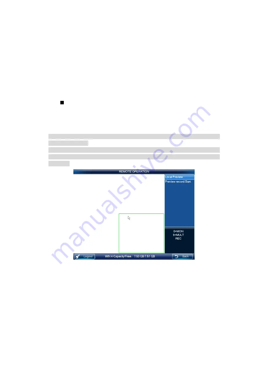
Please follow the steps listed below. 

Open remote operation/remote control->local real-time preview, click the button on the top 

left.   


Click 

 to start record,   


Click    to stop record.   


Click ESC button, system pops up the dialogue box asking you want to stop record 

and delete it now. Click the ENTER button or click the OK button on the dialogue box 

to delete. 

Note 


In  the  preview  mode,  click  the 

  button  directly;  system  begins  record  the  first 

window by default.   


In  anytime,  system  can  only  record  in  one  mode.  You  can  not  enable  these  two 

modes at the same time. The remote record stops once you exit the remote control 

interface.   


Figure 2-33 

The  local  USB  device  record  automatically  stops when  you  switch  the mode.  The  local 

record function can only be valid in the preview mode.   


When one record is in process, if you enable the other mode, you can see system pops up 

a dialogue box for  confirmation. You can click the  OK button to stop current record and 

then enable the new one.   


2.3.5.9  Remote Panel Simulation   

Содержание NKB

Страница 1: ...Network Keyboard Quick Start Guide V1 2 0 ...

Страница 2: ...u 11 2 2 1 Main Menu 11 2 2 2 System Settings 11 2 2 3 Device Manager 18 2 2 4 Input Settings 21 2 2 5 Output Settings 22 2 2 6 Account 23 2 2 7 Shutdown 24 2 3 User Operation Menu 25 2 3 1 Main Menu 25 2 3 2 Device List 25 2 3 3 Input List 26 2 3 4 Output List 27 2 3 5 Remote Operation Network Connection 29 2 3 6 Remote Operation RS232 37 2 3 7 Remote Operation RS485 37 2 3 8 Remote Control 38 2 ...

Страница 3: ...rd Simulator 46 2 4 Matrix Mode Detailed operation 47 2 4 1 Set Scheme 49 2 4 2 PTZ Control 52 2 5 Platform Mode Detailed Operation 52 2 5 1 Output video to the wall 60 2 5 2 PTZ Control 62 APPENDIX TOXIC OR HAZARDOUS MATERIALS OR ELEMENTS 64 ...

Страница 4: ...g our network keyboard This quick start guide is designed to be a reference tool for the operation of your system Before the operation please read the following safeguards and warnings carefully Please keep it well for future reference ...

Страница 5: ...tion 3 Installation Keep upwards Handle with care Do not place objects on the network keyboard 4 Qualified engineers needed All the examination and repair work should be done by the qualified service engineers We are not liable for any problems caused by unauthorized modifications or attempted repair 5 Environment The network keyboard should be used in a cool dry place away from direct sunlight in...

Страница 6: ...unction Function key Number and character 0 9 It is to input number and character Click the Shift button to switch ESC Cancel exit ENTER Confirm SHIFT Switch LOCK Work with SHIFT button to lock unlock the device Indication light Working power indication light POWER The light becomes on when the keyboard connects to the power Wire network indication light LINK The light becomes on when the keyboard...

Страница 7: ...umber button to select the output window MULT Working with the number button to select the window split mode CAM G Working with the number button to select the input group MON G Working with the number button to select the output group DVR Buttons TOUR PTZ control tour MULT Window split mode DEVC Working with number button to select remote device Record Record playback Stop record Stop record play...

Страница 8: ...ouch panel Display OSD Jog AUX menu or function buttons operation 1 3 Rear Panel This series products rear panel is shown as below See Figure 1 2 Figure 1 2 Please refer to the following sheet for detailed information 1 WIFI antenna 2 GND stud 3 RS422 RS485 port 4 Network port 5 VGA port 6 USB port 7 HDMI port 8 Audio output 9 Audio input 10 RS232 port 11 Power port 12 Power on off button ...

Страница 9: ...y boots up See Figure 2 1 Figure 2 1 2 1 1 1 General Mode Click General button you can see the login interface The factory default user name is admin and password is admin See Figure 2 2 Turn the jog inner dial to select the user name Turn the shutter outer ring to move the cursor to input the password Or you can use the mouse or touch panel to move the cursor to input the password Click the SHIFT...

Страница 10: ...es for each account For detailed operation contents please refer to Chapter 2 2 Admin Operation Menu and Chapter 2 3 User Operation Menu 2 1 1 2 Matrix Mode Click Matrix button you can see the following interface See Figure 2 3 Please input matrix information here Please refer to chapter 2 4 for detailed matrix mode operation Figure 2 3 2 1 1 3 Platform Mode ...

Страница 11: ...4 Figure 2 4 Click Login button you can see the following interface Here you can select TV wall you want to login from the dropdown list and then click OK button See Figure 2 5 Figure 2 5 Note You need to go to the DSS client end to set TV wall Please refer to the DSS manager user s manual for detailed information ...

Страница 12: ...See Figure 2 6 Figure 2 6 There are three ways for you to set You can set the device via the touch panel of the keyboard You can connect the mouse to the keyboard to use You can use the joystick to move the cursor or select the item For special menu item you can follow the prompt to click the ENTER button to confirm the operation or the ESC button to cancel current setup 2 2 2 System Settings The ...

Страница 13: ...2 1 General Settings In this interface you can set system time date language name and etc It includes the Y M D H M S setup You can move your cursor to the corresponding position and then input See Figure 2 8 Figure 2 8 ...

Страница 14: ... the cursor to the corresponding position and then use the number keys to change the setup Note Please note you need to have the router and enable the DHCP function before you use this function Figure 2 9 2 2 2 2 2 WLAN The wireless network is shown as in Figure 2 10 The wireless network setup steps are listed below 1 Click Refresh button system begins search hotspot again and automatically add pa...

Страница 15: ...disconnect current connection first and then connect again 3 Click OK button the WIFI working information can display current connection status after it successfully established the connection Figure 2 10 2 2 2 3 Hardware Settings Here you can set key sound key backlight auto lock time screen auto off time and etc See Figure 2 11 ...

Страница 16: ...15 Figure 2 11 2 2 2 4 Default Here you can check the corresponding item to restore factory default setup See Figure 2 12 Figure 2 12 ...

Страница 17: ...see the corresponding prompt Successfully calibrated 2 2 2 6 Backup From General settings Backup the admin can go to the USB device backup list interface See Figure 2 14 Import Please connect the USB device to the USB port and then check the box before the device name Click the Import box to import the configuration Export Please connect the USB device to the USB port and then check the box before...

Страница 18: ...m version build date SN information You can also upgrade the system See Figure 2 15 Please connect the device to the USB port and then click the Start button to begin the upgrade operation Note Before the operation please make sure your upgrade file name is update bin ...

Страница 19: ...etect After the detect you can see device manager interface Here you can see controlled device name IP address port device type status and etc You can add modify and delete the device See Figure 2 16 Figure 2 16 IP Search 1 Click IP search button you can go to the IP search interface See Figure 2 17 ...

Страница 20: ... the box to select a device and then input the user name and password click the Add button to add a device You can use the IP segment setup function on the IP search interface to quickly find the device IP you want to add It supports 8 criteria In this way you can narrow the IP segment and quickly and accurately find the device See Figure 2 18 ...

Страница 21: ...ed the device its initial status is null You can view the device current status after you added it System says the device has been added means it is in the Device manager list now Manual Add Note The manual add function supports private protocol and ONVIF function 1 Click Manual Add button system pops up the following interface See Figure 2 19 ...

Страница 22: ...o complete add process Modify and delete Modify Select the device first and then click the Modify button you can see system pops up an interface for you to change the information Here you can modify device SN port number user name and password Note The user name and password here is for the keyboard to login the device It does not change the user name and password of the keyboard itself Delete Sel...

Страница 23: ...orresponding channel name of the device The SN of the monitor position name shall unique Otherwise system may pop up a dialogue box The channel name shall be unique Please input again 2 2 5 Output Settings Click output settings button you can go to the corresponding interface See Figure 2 21 Modify In output settings interface click Modify button you can go to the corresponding interface to change...

Страница 24: ...lete modify device The user management rights include add delete modify user and set devices for each user There are two modes for you to allocate the devices to the user By device by channel Note You can switch to allocate devices by channel mode from by device mode But you can not switch to allocate devices by device mode from by channel mode The user account can only have the operation rights a...

Страница 25: ... add the new user You need to input the user name and password Modify User Select an ordinary user from the list and then click the Modify user button you can go to the corresponding interface Here you can add or delete the device current user controls 2 2 7 Shutdown Click the Shutdown button you can see system pops up a dialogue for you to confirm the operation You can logout the menu shutdown th...

Страница 26: ...er menu includes device list input list output list operation advanced control playback matrix control and analog keyboard See Figure 2 24 Figure 2 24 2 3 2 Device List Click Device List button you can view the device that current user can control See Figure 2 25 ...

Страница 27: ...26 Figure 2 25 2 3 3 Input List Here you can view the channel information of controlled device See Figure 2 26 Note The channel name displayed here is the name system gets from the device Figure 2 26 ...

Страница 28: ... select the group SN and then go to the group interface There are 16 input groups and you can add delete the monitor positions You can also set the tour interval Note This operation is mainly for the decoder group Please refer to chapter 2 3 5 3 Decoder Operation for detailed information Figure 2 27 2 3 4 Output List Click Output list button you can go to the following interface See Figure 2 28 ...

Страница 29: ...e 2 28 Group Click Group button you can go to the following interface See Figure 2 29 You can select the group SN and then go to the group interface There are 16 output groups and you can add delete Figure 2 29 ...

Страница 30: ...on ESC button have the delete function You can use it to remove the latest input number Output screen No MON Select output screen Input source No CAM Select video source to output to the wall Input source No PT Open video from one channel 0 MON Open local preview 0 CAM Close video source of one window 0 PT Go to 485 control 0 DEV Go to 232 control device SHIFT Full screen 2 3 5 1 Shortcut Operatio...

Страница 31: ...w 2 Input number j MULT it is to output the signal from channel i to display in j window mode Output to the video wall It is to display the signal from the selected channel via the decode output channel Please follow the steps listed below 1 Input number i MON it is to select output channel i 2 Input number j WIN it is to select current output window 3 Input number k CAM it is to output the input ...

Страница 32: ...ect to output the current input group k to the output channel window j to enable the tour function Decode video to the video wall Input group output group You can refer to the above contents for detailed information If the channel amount n in the input group is smaller than or equal to the output window amount m in the output group for example output group 1 has two output channels and each output...

Страница 33: ...OOM slow speed by one level See Figure 2 30 Figure 2 30 If you click PLAY PAUSE or STOP without selecting a window system begins or stops playback of the first window by default Note Right now system supports control decoder playback remotely It does not support the local playback function 2 3 5 5 PTZ In the PTZ control mode you cam use the network keyboard to control the PTZ operation The interfa...

Страница 34: ...ing and PTZ Please refer to the following sheet for detailed information Button Function Number Input step preset and etc Joystick Control PTZ direction Shuttle Outer ring Zoom Jog Inner dial Focus Aperture Light Wiper GOTO Call preset PATTERN Pattern start Stop TOUR Tour start Stop AUTOPAN Pan start Stop ESC Esc 2 3 5 6 Audio Talk You can use the audio talk function to realize the bidirectional t...

Страница 35: ...specified device See Figure 2 32 Click AUX button to stop the bidirectional talk Figure 2 32 2 3 5 7 Snapshot The snap function can only be valid in preview mode The snap picture saved in the USB device or a FTP server USB device has the higher priority Please refer to chapter 2 3 9 3 for snapshot setup Please follow the steps listed below 1 Input number i WIN it is to select the window i for the ...

Страница 36: ... box asking you want to stop record and delete it now Click the ENTER button or click the OK button on the dialogue box to delete Note In the preview mode click the button directly system begins record the first window by default In anytime system can only record in one mode You can not enable these two modes at the same time The remote record stops once you exit the remote control interface Figur...

Страница 37: ...pause Play normally when it is backward playing or in pause mode Play when it is in pause mode Backward play pause Play backward when it is in normal playback or in pause mode Click it to pause playback when it plays backward Play previous When playback click it to play the previous file In menu setup interface you can skip to the previous item Play next When playback click it to play the next fil...

Страница 38: ...he Function item please select net keyboard from the dropdown list You need to set the baud rate stop bit data bit parity and etc System default setup is Baud rate 9600 Data bit 8 Stop bit 1 Parity none 3 For the keyboard from the Advanced COM here you can input remote address baud rate data bit stop bit and parity Note Remote address It is a SN for the front end to detect It is the DVR No in the ...

Страница 39: ...an set protocol address baud rate data bit stop bit parity and etc You can select the protocol according to your speed dome and RS485 address is the same as the speed dome 5 Please save current setup 2 3 7 2 Operation In this mode you can use the network keyboard to control the PTZ of the speed dome Please input the number 0 PT to enable PTZ control Please refer to chapter 2 3 5 5 Pan Tilt Zoom fo...

Страница 40: ...nput channel on the input list or you can drag one channel to a window directly Now you can preview the video from the selected channel on current window 2 3 8 2 Decoder Mode On the decoder mode the video from one input channel can be decoded and then output to an output channel Please follow the steps listed below 1 Double click an output channel from an output list Not local preview 2 Select win...

Страница 41: ...hot current video and save as one picture You can press button at the top of the joystick to snapshot The picture can be saved on the flash disk or on a FTP server For detailed snapshot setup information please refer to chapter 2 3 9 6 Close preview Click it to close current preview video Close window Click it to close current window Close all Click it to close all windows Open all Click it to ope...

Страница 42: ... password interface is for you to change the password of current user Please input the old password first and then input the new password and confirm You can click OK button to save new password See Figure 2 38 Figure 2 38 2 3 9 3 AUX Settings ...

Страница 43: ...ut the corresponding number AUX to enable the function Figure 2 39 Note System default AUX button setup is 0 to enable snapshot and 1 to enable bidirectional talk 2 3 9 4 Decode Settings Click decode settings button you can go to decode setting interface See Figure 2 40 You can select the channel name and decode type from the dropdown list The type includes RT real time priority RT good general RT...

Страница 44: ...ecified macro Click Add button you can go to the corresponding interface You can input customized macro name one by one and then click the Save button Note For the macro already exists it is read only Some keys do not support macro 2 3 9 6 Snapshot In this interface you can save snapshot picture on a FTP server Please follow the steps listed below 1 Click Snapshot button on the Advanced interface ...

Страница 45: ...rity That is to say all snapshot pictures will be saved on the FTP server The snapshot function is null if the FTP service and the flash disk are not available 3 Click Test button system begins FTP test You can see connection is OK once you see the corresponding interface 4 Click OK button you can complete snapshot function 2 3 9 7 Backup In this interface you can set pre record time of the monito...

Страница 46: ... you can search playback detect backup or delete the saved records The playback function supports record from local USB device record playback or the record from the remote storage device to be playback on the network keyboard During the playback it supports fast play slow play or backup the records to the USB device Figure 2 44 ...

Страница 47: ...Figure 2 45 Here you can switch channel Figure 2 45 2 3 12 Keyboard Simulator Note Please makes sure your setup such as baud rate data bit on the RS232 Main menu Advanced RS232 are the same as the setup of the M60 On the operator main menu click keyboard simulator you can see the following interface See Figure 2 46 You can u control the M60 ...

Страница 48: ...eme No PLAN Switch scheme Output screen No MON Switch output screen Input source No CAM Switch input source Click OPEN button Use PTZ control Preset No SHOT Call preset Select PROGRAM mode on the left corner Preset No SHOT Set preset 2 4 Matrix Mode Detailed operation Matrix mode interface is shown as in Figure 2 47 ...

Страница 49: ...l tour and close preview operation of is for the whole selected area Click number 0 MON is to close all video source on the selected screen and at the same time system updates the contents of the screen such as window split mode tour time and etc Double click the splicing video wall you want to operate or input number i MON on the keyboard you can see an interface shown as below See Figure 2 48 ...

Страница 50: ...control Menu Implement tour control and close preview operation Device information Click it to view device information or scheme SN Note Here is to open all the contents you set on the matrix end Click number 0 MON on the keyboard is to close all video sources of current screen 2 4 1 Set Scheme Scheme is for you to set video wall information such as window display mode video source information tou...

Страница 51: ...n available and the window is in current screen set this window as current one If there is a screen available but the window is not in the screen then system switches to the screen that contains the window and set this window as current one 2 Input number k CAM on the keyboard or select one channel and drag it to the window you selected in the first step you can output the video to the window you ...

Страница 52: ...ger than the output channel amount system enables tour automatically See Figure 2 50 Figure 2 50 Click the control tour of the or click the TOUR on the keyboard you can close the tour of the whole screen Click Control tour or TOUR button again you can enable tour function again Free window On the matrix mode you can use network keyboard to open window at anywhere you want See Figure 2 51 ...

Страница 53: ...rrent scheme setup If you have not save click reload button you can go back to previous setup Click Close video button you can close splicing video on the matrix end 2 4 2 PTZ Control In the PTZ control mode you cam use the network keyboard to control the PTZ operation The interface is the same as when you are controlling via the Web You can view the video from the control channel on the left pane...

Страница 54: ... Figure 2 53 3 In Figure 2 53 input user name and password click Login button System default admin user name is system and the password is 123456 For your security please change your password after first login 4 On the WEB from General Account you can click Add button to add a new role See Figure 2 54 Here you can add a new role and use it to create new user Check the reuse button in Figure 2 55 s...

Страница 55: ...54 Figure 2 54 Figure 2 55 ...

Страница 56: ...60 Note You can only see the Org Channel SN after you implement according to step 5 This control SN can be modified if necessary The keyboard can use it to switch videi source in the future Click the edit button red highlighted in Figure 2 57 you can select camera type Figure 2 57 Figure 2 58 Please check the box to enable splicing function when you are adding the decoder See Figure 2 59 Figure 2 ...

Страница 57: ... TV wall you can add TV wall layout splicing bind decode channel and etc See Figure 2 60 Figure 2 60 8 Open the platform client you downloaded at step 2 and use the account you created in step 4 to login See Figure 2 61 Figure 2 61 ...

Страница 58: ... and then bind to save it as a task Figure 2 62 10 On the network keyboard select platform mode you can see an interface shown as in Figure 2 63 Figure 2 63 11 Input DSS platform IP address user name password according to the information in step 1 and step3 click login See Figure 2 64 ...

Страница 59: ...wall you set in step 7 and then click OK button You can go to the platform control mode via the network keyboard See Figure 2 65 Figure 2 65 13 Select the task list on the right pane and double click to load the scheme See Figure 2 66 ...

Страница 60: ...59 Figure 2 66 Double click a screen or click number i MON you can see an interface shown as in Figure 2 67 Figure 2 67 Please refer to the following sheet for detailed information SN Name Function ...

Страница 61: ...our control close preview Enable disable tour function Keyboard has the operation mode edit mode In edit mode you can modify tour plan and add video source to the tour group Maximize decode window Select a screen double click or click ENTER button you can maximize the screen or restore original size Close the video source of one window Select a window click Close preview button or input 0 CAM Clos...

Страница 62: ...current one If there is a screen available and the window is in current screen set this window as current one If there is a screen available but the window is not in the screen then system switches to the screen that contains the window and set this window as current one 2 Input number k CAM on the keyboard or select one channel and drag it to the window you selected in the first step you can outp...

Страница 63: ...to the DSS once you set on the keyboard and click output video button Click save scheme button you can save current scheme setup If you have not save click reload button you can go back to previous setup Click Close video button you can close current selected video on the TV wall 2 5 2 PTZ Control In the PTZ control mode you can use the network keyboard to control the PTZ operation The interface i...

Страница 64: ...63 ...

Страница 65: ...dicates that the concentration of the hazardous substance of at least one of all homogeneous materials in the parts is above the relevant threshold of the SJ T11363 2006 standard Note This quick start guide for reference only Slight difference may be found in user interface All the designs and software here are subject to change without prior written notice All trademarks and registered trademarks...

Отзывы: