170
Line1/2/3/4: System supports four tripwires. Each SN stands for one tripwire.
Direction (
/
/
): System can generate an alarm once there is any object
crossing in the specified direction.
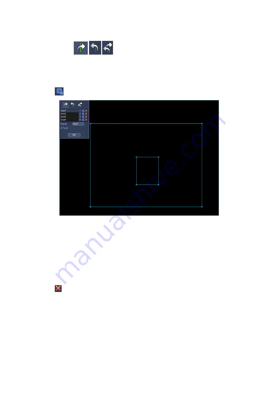
Now you can draw a rule. Left click mouse to draw a tripwire. The tripwire can be a direct
line, curve or polygon. Right click mouse to complete.
Click
to draw filter object.
Figure 4-115
Select the blue line and then use mouse to adjust zone size.
Note
Each rule can set two sizes (min size/max size). Once the object is smaller than the min
size or larger than the max size, there is no alarm. Please make sure the max size is
larger than the min size.
Click Ok to complete the rule setup.
Tips
Click
to delete the corresponding rule.
You can refer to the following information to set other parameters.
Channel: Select a channel from the dropdown list to set tripwire function.
Enable: Check the box here to enable tripwire function.
Rule: input customized rule name here.
Period: Click set button, you can see an interface is shown as in Figure 4-107. Here
you can set tripwire period. System only enables tripwire operation in the specified
periods. There are two ways for you to set periods. Please note system only supports
6 periods in one day.
Содержание HDCVI series
Страница 1: ...Dahua HDCVI Standalone DVR User s Manual Dahua HDCVI Standalone DVR User s Manual V1 6 1 ...
Страница 172: ...162 Figure 4 104 Figure 4 105 ...
Страница 173: ...163 Figure 4 106 Figure 4 107 ...
Страница 189: ...179 Figure 4 124 Figure 4 125 ...
Страница 190: ...180 Figure 4 126 Figure 4 127 ...
Страница 191: ...181 Figure 4 128 Figure 4 129 ...
Страница 194: ...184 Figure 4 133 Figure 4 134 ...
Страница 201: ...191 Figure 4 144 Figure 4 145 4 11 4 1 2 2Trigger Snapshot ...
Страница 203: ...193 Figure 4 147 Figure 4 148 4 11 4 1 2 3Priority ...
Страница 220: ...210 Figure 4 169 For digital channel the interface is shown as below See Figure 4 170 Figure 4 170 4 11 5 6 ATM POS ...
Страница 234: ...224 Figure 4 187 ...
Страница 252: ...242 Figure 5 26 5 8 2 Network 5 8 2 1 TCP IP The single Ethernet port interface is shown as in Figure 5 27 Figure 5 27 ...
Страница 269: ...259 Figure 5 55 Figure 5 56 ...
Страница 282: ...272 Figure 5 71 Figure 5 72 ...
Страница 289: ...279 Figure 5 81 Figure 5 82 Figure 5 83 Please refer to the following sheet for detailed information ...
Страница 332: ...322 448K 196M 512K 225M 640K 281M 768K 337M 896K 393M 1024K 450M 1280K 562M 1536K 675M 1792K 787M 2048K 900M ...


