96
Item
Note
from 0 to 100. The default value is 50.
The larger the number, the higher the contrast is. You
can use this function when the whole video bright is OK
but the contrast is not proper. Please note the video may
become hazy if the value is too low. If this value is too
high, the dark section may lack brightness while the
bright section may over exposure .The recommended
value ranges from 40 to 60.
Saturation
It is to adjust monitor window saturation. The value
ranges from 0 to 100. The default value is 50.
The larger the number, the strong the color is. This value
has no effect on the general brightness of the whole
video. The video color may become too strong if the
value is too high. For the grey part of the video, the
distortion may occur if the white balance is not accurate.
Please note the video may not be attractive if the value
is too low. The recommended value ranges from 40 to
60.
Gain
The gain adjust is to set the gain value. The default
value may vary due to different device models. The
smaller the value, the low the noise. But the brightness is
also too low in the dark environments. It can enhance
the video brightness if the value is high. But the video
noise may become too clear.
Color mode
It includes several modes such as standard, color, bright,
gentle. Select a color mode, the sharpness, brightness,
contrast
and
etc
can
automatically
switch
to
corresponding setup.
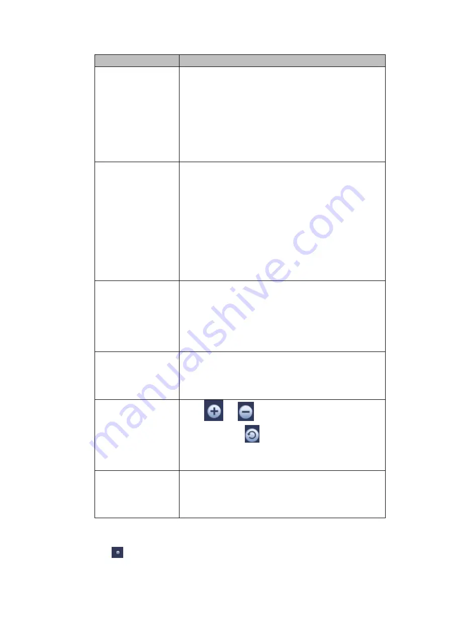
EQ
Click
or
to adjust image equalization value.
Click reset button
, system can auto adjust the video
to the best effect.
This function is for analog channel only.
Image position
It is to adjust the image position on the screen. The
value here refers to the pixel. The default pixel value is
16.
This function is for analog channel only.
4.5.6 Display
It is to set display output mode. There are two modes: full screen (4:3)/image original rate
(16:9). Icon
means current display output mode. See Figure 4-30.
Содержание HDCVI series
Страница 1: ...Dahua HDCVI Standalone DVR User s Manual Dahua HDCVI Standalone DVR User s Manual V1 6 1 ...
Страница 172: ...162 Figure 4 104 Figure 4 105 ...
Страница 173: ...163 Figure 4 106 Figure 4 107 ...
Страница 189: ...179 Figure 4 124 Figure 4 125 ...
Страница 190: ...180 Figure 4 126 Figure 4 127 ...
Страница 191: ...181 Figure 4 128 Figure 4 129 ...
Страница 194: ...184 Figure 4 133 Figure 4 134 ...
Страница 201: ...191 Figure 4 144 Figure 4 145 4 11 4 1 2 2Trigger Snapshot ...
Страница 203: ...193 Figure 4 147 Figure 4 148 4 11 4 1 2 3Priority ...
Страница 220: ...210 Figure 4 169 For digital channel the interface is shown as below See Figure 4 170 Figure 4 170 4 11 5 6 ATM POS ...
Страница 234: ...224 Figure 4 187 ...
Страница 252: ...242 Figure 5 26 5 8 2 Network 5 8 2 1 TCP IP The single Ethernet port interface is shown as in Figure 5 27 Figure 5 27 ...
Страница 269: ...259 Figure 5 55 Figure 5 56 ...
Страница 282: ...272 Figure 5 71 Figure 5 72 ...
Страница 289: ...279 Figure 5 81 Figure 5 82 Figure 5 83 Please refer to the following sheet for detailed information ...
Страница 332: ...322 448K 196M 512K 225M 640K 281M 768K 337M 896K 393M 1024K 450M 1280K 562M 1536K 675M 1792K 787M 2048K 900M ...


