background image

Installation    4 


Installation 

 Installation Requirement 

3.1.1 Notice 


Do  not  install  the  VTO  to  places  with  condensation,  high  temperature,  grease  or  dust, 

chemical corrosion, direct sunlight, or zero shelter. 


The  installation  and  adjustment  must  be  finished  by  professional  crew,  and  do  not 

disassemble the VTO. 

3.1.2 Guidance 

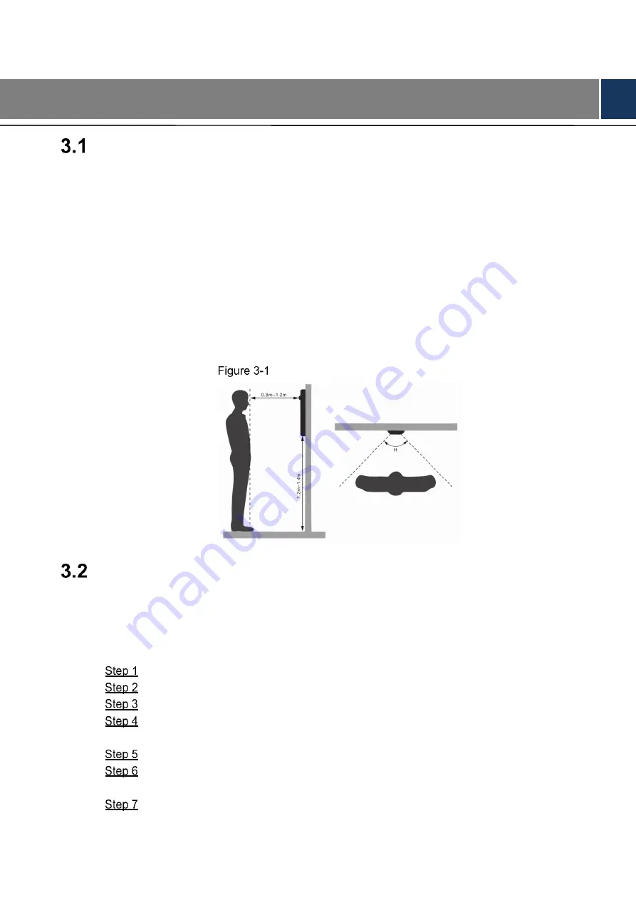
See Figure 3-1 for the reference of the installation position. The VTO horizontal angle of view 

varies with different model, try to face the center of the VTO as much as possible. 

 Installation position reference 


 Installing Process 

The VTO can be installed on the wall or in the wall. 

3.2.1 Installed on the Wall 

  With the help of installation diagram, hammer four expansion screws into the wall. 

  Install the waterproof pad on the mounting box from the back of the mounting box. 

  Put four waterproof rings on four ST4×25 self-tapping screws. 

  Install the mounting box on the wall by screw the four ST4×25 self-tapping screws into 

the expansion screws. 

  Put the VTO into the mounting box. 

  Fix the VTO to the mounting box by screwing two M3×8 screws from the bottom of the 

mounting box. 

  Apply silicone sealant to gaps between the device and the wall. 

Содержание DHI-VTO2202F-P

Страница 1: ...VTO2202F Version 1 0 Quick Start Guide V1 0 0...

Страница 2: ...gularly change the credentials to your devices to help ensure that only authorized users are able to access the system 2 Change Default HTTP and TCP Ports Change default HTTP and TCP ports for systems...

Страница 3: ...nly temporarily for tracing and testing purposes only 10 Multicast Multicast is used to share video streams between two recorders Currently there are no known issues involving Multicast but if you are...

Страница 4: ...t liable for any loss caused by the operations that do not comply with the Guide The Guide would be updated according to the latest laws and regulations of related regions For detailed information see...

Страница 5: ...d IV Please visit our website contact the supplier or customer service if there is any problem occurred when using the device If there is any uncertainty or controversy please refer to our final expla...

Страница 6: ...n t put on the device anything filled with liquids in order to prevent liquids from flowing into the device Install the device at well ventilated places don t block its ventilation opening Use the dev...

Страница 7: ...2 1 Installed on the Wall 4 3 2 2 Installed in the Wall 6 4 Configuration 8 Configuration Process 8 Config Tool 8 Configuring VTO 8 4 3 1 Initialization 8 4 3 2 Configuring VTO Number 9 4 3 3 Configu...

Страница 8: ...Network Diagram 1 1 Network Diagram...

Страница 9: ...nputs audio 2 Camera Monitors door area 3 Indicator When you are calling this indicator will be on 4 Indicator During the call communication this indicator will be on 5 Indicator When the door is unlo...

Страница 10: ...communication RS485_A RS 485 communication ALARM_NO Switch quantity output ALARM_COM Switch quantity output EOC2 Two wire port EOC1 Two wire port 3 DOOR_BUTTON Unlock button DOOR_FEEDBACK Door contact...

Страница 11: ...as much as possible Installation position reference Installing Process The VTO can be installed on the wall or in the wall 3 2 1 Installed on the Wall With the help of installation diagram hammer four...

Страница 12: ...5 Installed on the wall Table 3 1 Names of numbers 1 No Name 1 VTO 2 Waterproof ring 3 ST4 25 self tapping screw 4 Mounting box 5 M3 8 Screw 6 Waterproof pad 7 Expansion screw 8 Wall Apply silicone se...

Страница 13: ...ng two M3 8 screws into the VTO from the bottom of the mounting box front cover Put the mounting box front cover with VTO into the mounting box rear cover Put waterproof rings to the M3 8 screws Screw...

Страница 14: ...Installation 7 Table 3 2 Names of numbers 2 No Name 1 M3 8 Screw 2 Waterproof ring 3 VTO 4 Mounting box front box 5 Mounting box rear box 6 Wall...

Страница 15: ...up call See 4 3 5 Configuring Call No and Group Call 6 Add VTO devices to the SIP server See 4 3 6 Adding VTO Devices 7 Add room number to the SIP server See 4 3 7 Adding Room Number Configure VTH See...

Страница 16: ...e initialization succeeded Click OK The login interface is displayed See Figure 4 2 Login interface 4 3 2 Configuring VTO Number The VTO number can be used to differentiate each VTO and it is normally...

Страница 17: ...vice properties In the VTO No input box enter the VTO number you planned for this VTO and then click Confirm to save 4 3 3 Configuring Network Parameters Select Network Setting Basic The TCP IP inform...

Страница 18: ...as SIP server Select the Enable check box at SIP Server and then click Save The VTO will reboot and after rebooting you can then add VTO and VTH devices to this VTO See 4 3 6 Adding VTO Devices and 4...

Страница 19: ...adding VTO and VTH Select Local Setting Basic The device properties are displayed See Figure 4 7 Device properties In the Villa Call No input box enter the room number you need to call and then click...

Страница 20: ...VTO No Management The VTO No Management interface is displayed See Figure 4 9 VTO No management Click Add The Add interface is displayed See Figure 4 10 Add VTO Configure the parameters and be sure t...

Страница 21: ...them to the network This section applies to the condition in which a VTO device works as SIP server and if you use other servers as SIP server see the corresponding manual for the detailed configurati...

Страница 22: ...hould be room number 0 and the room number of the extension VTH should be room number 1 room number 2 and so on You can have 9 extension VTH devices at most for one master VTH Register Type Select pub...

Страница 23: ...H to answer the call 4 4 2 Doing Monitor from VTH In the main interface of the VTH select Monitor Door The Door interface is displayed See Figure 4 14 Door Select the VTO you need to do monitor The mo...

Страница 24: ...Configuration 17 Monitor screen...

Страница 25: ...the villa VTO there will be push message on your phone and you can talk to the visitor or unlock the door remotely on your phone Scan the following QR code to download and install the app QR code Run...

Страница 26: ...nd then select Network The P2P interface is displayed See Figure 5 4 For VTO3211D select Household Setting Room No Management to get the QR code P2P Scan the QR code with your phone then enter the use...

Страница 27: ...hone App 20 Live Tap Alarm Manager Subscribe and then subscribe the VTO you need See Figure 5 6 Subscribe When someone is calling you from the subscribed villa VTO there will be push message on your p...

Страница 28: ...Connecting Mobile Phone App 21 Push...

Отзывы: