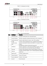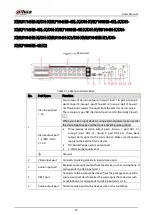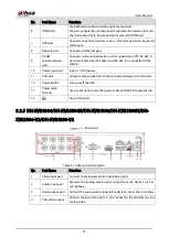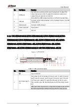
User’s Manual
42
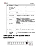
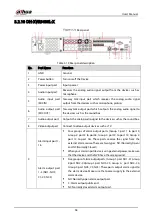
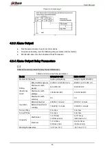
No.
Port Name
Function
6
Alarm input port 1–
16
Four groups of alarm output ports (Group 1: port 1 to port 4;
Group 2: port 5 to port 8; Group 3: port 9 to port 12; Group 4:
port 13 to port 16). These ports receive the signal from the
external alarm source. There are two types; NO (Normally Open)
and NC (Normally Closed).
When your alarm input device is using external power, make sure
that the device and the NVR have the same ground.
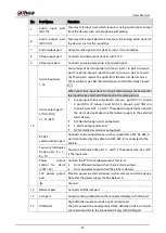
Alarm output port
1–5 (NO1–NO5;
C1–C5; NC5)
Five groups of alarm output ports. (Group 1: port NO1–C1,Group
2:port NO2–C2,Group 3:port NO3–C3, Group 4
:
port NO4–C4,
Group 5: port NO5, C5, NC5). These ports output alarm signal to
the alarm device. Make sure that power supply to the external
alarm device.
NO: Normally open alarm output port.
C: Alarm output public end.
NC: Normally closed alarm output port.
RS-485
communication
port
You can connect to the control devices such as speed dome PTZ. RS-
485_A port is connected by the cable A and RS-485_B is connected
to the cable B.
Four-wire full-
duplex RS-485 port
(T+, T-, R+, R-)
Four-wire full-duplex 485 port. T+ and T- is the output wire; R+ and R-
is the input wire.
Control power
output (CTRL 12V)
Controls the 6
th
channel power output for alarm.
Turns off power output when there is alarm output.
Turns on power output when the alarm is cleared.
12V power output
port
Provides power to external devices such as camera and alarm device.
Note the supplying power shall be below 1 A.
G
Ground.
7
RS-232 debug
COM.
It is for general COM debug to configure IP address or transfer
transparent COM data.
8
VGA video output
Outputs analog video signal. It can connect to the monitor to view
analog video.
9
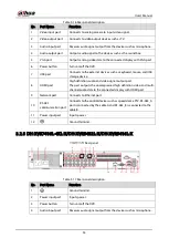
Power button
Turns on/off the Device.
10
Power input port
Inputs power.
11
Loop out
Outputs the video signal of the corresponding video input port.
12
Video input port
Connect to analog camera to input video signal.
13
Network port
Connects to Ethernet port.
14
USB port
Connects to the external devices such as keyboard, mouse, and USB
storage device.
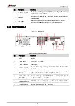
15
eSATA port
External SATA port which connects to the device with SATA port.
Perform the jumper configuration when connecting HDD.
Содержание XVR Series
Страница 1: ...Digital Video Recorder User s Manual V1 5 0 ZHEJIANG DAHUA VISION TECHNOLOGY CO LTD...
Страница 20: ...User s Manual 8 Fix HDD Connect cables Install the bracket and then fasten the screws...
Страница 115: ...User s Manual 103 Main menu...
Страница 201: ...User s Manual 189 Search result diagram Search result list...
Страница 221: ...User s Manual 209 Search results diagram Search results list Double click the video or click...
Страница 240: ...User s Manual 228 List For the data displayed in graph see Figure 5 187 Graph...
Страница 283: ...User s Manual 271 Main stream Sub stream...
Страница 327: ...User s Manual 315 Login Click Forgot Password Reset password Click OK...
Страница 339: ...User s Manual 327 Abbreviations Full term VBR Variable Bit Rate VGA Video Graphics Array WAN Wide Area Network...
Страница 357: ...User s Manual 345 Neutral cable...
Страница 362: ...User s Manual 350 Enable IP MAC address filtering function to limit the range of hosts allowed to access the device...
Страница 363: ...User s Manual...

