8.Features
© China Daheng Group, Inc. Beijing Image Vision Technology Branch 141
TimerDelay
Timer1
Timer1Active
TimerTrigger
Source
ExpsoureStart
Figure 8-50 Timer1Active schematic diagram
The timer configuration process is as follows:
1. Set TimerSelector, currently only Timer1 supported.
2. Set LineSelector.
3. Set the LineSource to Timer1Active.
4. Set TimerTriggerSource, currently only ExposureStart supported.
5.
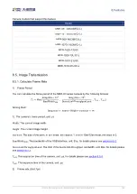
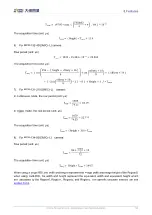
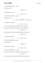
Set TimerDelay, the range of TimerDelay is [0, 16777215], the unit is μs.
6.
Set TimerDuration, the range of TimerDuration is [0, 16777215], the unit is μs.
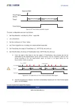
1) From the start of the timer to the full output of Timer1Active, this process will not be
interrupted by the Exposure
Start signal, and Timer1Active must be completely output to start
timing according to the next ExposureStart signal. As shown in the figure below, the red
ExposureStart signals are ignored.
TimerDelay
Timer1
Timer1Active
TimerTriggerSource
ExpsoureStart
TimerDelay
ExpsoureStart
Figure 8-51 The relationship of Timer1Active and ExposureStart signal
2) After the acquisition is stopped, the timer is immediately cleared and the Timer1Active signal
goes low immediately.
Camera models that support this feature:
Model
MER-302-56U3M/C(-L)


