7.Electrical Interface
© China Daheng Group, Inc. Beijing Image Vision Technology Branch 97
1
2
8
7
6
4
5
3
3.3V
Line2
FPGA INPUT2
Camera internal circuit
External circuit
Signal
output
Power +
PWR GND
NPN
Pull-up
resistor
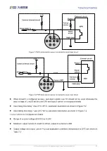
Figure 7-7 NPN photoelectric sensor connected to Line2 input circuit
1
2
8
7
6
4
5
3
3.3V
Line2
FPGA INPUT2
Camera internal circuit
External circuit
Signal
output
Power +
PWR GND
PNP
Pull-down
resistor
Camera GND
Figure 7-8 PNP photoelectric sensor connected to Line2 input circuit
When LIine2/3 is configured as input, pull-down resistor over 1K should not be used, otherwise the
input voltage of Line2/3 will be over 0.6V and logic 0 cannot be recognized stably
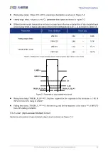
Input rising time delay: <2μs (0°C~45°C), parameter description as shown in Figure 7-2
Input falling time delay: <2μs (0°C~45°C), parameter description as shown in Figure 7-2
7.3.3.2. Line2/3 is Configured as Output
Range of external voltage (EXVCC) is 5~24V
Maximum output current of Line2/3 is 25mA, output impedance is 40Ω
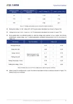
Output voltage and output current in typical application conditions (temperature is 25
℃
) are shown in

