7.Electrical Interface
© China Daheng Group, Inc. Beijing Image Vision Technology Branch 91
7. Electrical Interface
7.1. LED Light
An LED light is set on the back cover of camera which indicates camera's status, as shown in Table 7-1.
LED light can display 3 colors: red, yellow and green.
LED status
Camera status
Off
The camera is powered off
Solid red
The camera is not boot-loaded
Flashing red
The camera is in low power consumption mode
Solid green
The camera has been boot-loaded, but no data is being transmitted
Flashing green
Data is being transmitted
Flashing yellow
The camera's initialization failed
Table 7-1 Camera status
7.2. USB Port
Recommend to use the cables officially recognized by USB IF.
7.3. I/O Port
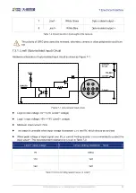
I/O port is implemented by Hirose 8-pin receptacle (No. HR25-7TR-8PA (73)), and the corresponding plug
is HR25-7TP-8S.
Diagram
Pin
Definition
Core Color
Description
1
Line0+
Green
Opto-isolated input +
2
GND
Blue
GPIO GND
3
Line0-
Grey
Opto-isolated input -
4
NC
Purple
NC
5
Line2
Orange
GPIO input/output
6
Line3
Pink
GPIO input/output


