background image

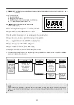
1. Incomplete segments,

1) Segments missing.
2) Partical segments missing.
3) Digit flickering other than normal display slight flickering.
4) " : 0 " does not display when power is on.

2. A distinct change in the diplay are not on when they

numbers is the display.

3. One or more digits in the diplay are not on when they should be.

4. Display indicates a number different from one touched.

5. Specific numbers (for example 2 or 3) will not display when the panel is touched.

6. Display does not count down or up with time cooking or clock operation.

7. Oven is programmable and cooks normally but no display shows.

8. Display obviously jumps in time while counting down.

9. Display counts down noticeably too fast while cooking.

10. Display does not show the time of day when clear pad is touched.

11. Oven lamp and turntable motor do not stop although cooking is finished. Check if the RELAY 2 contacts close if they

are close, replace touch control circuit.

20

( TROUBLE 4 ) The following visual conditions indicate a probable defective touch control circuit or membrane switch

assembly

NOTE
Before following the particular steps listed above in the trouble shooting guide for the membrane keyboardís,
failure, please check for the continuity of each wire-harness between the membrane keyboard and P.C.B.
assembly.

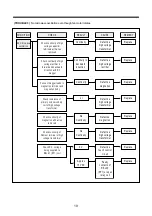
CON DITION 

CHECK RE

SULT 

CAUSE 

REM EDY

D isplay  does 

not show

program m ing 
at all,    even if 

keyboard is 

touched.

N orm al

R eplace

control box 

sub-a ssem bly

R eplace the

m em brane

keyboard

M alfunction

of touch

control circuit
of control box

sub-a ssem bly

A bnorm al

C heck eac h pad  for

continuity of the

m em brane keyboard 

for the follow ing 
keyboard check

proce dure

M alfunction of

the m em brane

keyboard

Содержание KOR-164H0A

Страница 1: ...No R164H0A002 Apr 2007 Caution In this Manual some parts can be changed for improving their performance without notice in the parts list So if you need the latest parts information please refer to PPL Parts Price List in Service Information Center http svc dwe co kr ...

Страница 2: ...ock monitor door seal and microwave generation and transmission systems shall be repaired replaced or adjusted by procedures described in this manual before the oven is released to the owner e A microwave leakage check to verify compliance with the Federal performance standard should be per formed on each oven prior to release to the owner TABLE OF CONTENTS SAFETY AND PRECAUTIONS 2 1 FOR SAFE OPER...

Страница 3: ...to servicing the oven 2 If any certified oven unit is found to servicing a microwave emission check should be performed prior to servic ing the oven a inform the manufacturer importer or assembler b repair the unit at no cost to the owner c attempt to ascertain the cause of the excessive leakage d tell the owner of the unit not to use the unit until the oven has been brought into compliance 3 If t...

Страница 4: ... FREQUENCY 2450MHz OUTSIDE DIMENSIONS W X H X D 589 x 339 x 486 mm 23 2 x 13 3 x 19 1 in CAVITY DIMENSIONS W X H X D 399 x 263 x 426 mm 15 7 x 10 4 x 16 8 in NET WEIGHT APPROX 18 5 Kg 40 8 lbs TIMER 99 min 99 sec FUNCTION SELECTIONS MICROWAVE POWER SELECTIONS 10 LEVELS CAVITY VOLUME 1 6 Cu Ft SPECIFICATIONS ARE SUBJECT TO CHANGE WITHOUT NOTICE SPECIFICATIONS ...

Страница 5: ...4 EXTERNAL VIEW 1 OUTER DIMENSION ...

Страница 6: ...icrowave cannot pass through perforations in screen 4 4 SPATTER SHIELD Protects the microwave outlet from splashes of cooking foods 5 5 OVEN LAMP Automatically turns on during oven operating 6 6 SAFETY INTERLOCK SYSTEM 7 7 CONTROL PANEL 8 8 GLASS COOKING TRAY Made of special heat resistant glass The tray must always be in proper position before operating Do not cook food directly on the tray 9 9 O...

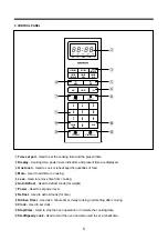
Страница 7: ...er level 8 Defrost Used to defrost foods for time 9 Kitchen Timer Used as a minute timer delay cooking hold setting after cooking 0 Clock Used to set clock q Stop Clear Used to stop the oven operation or to delete the cooking data w Start Speedy cook Used to start the oven and also used to set a reheat time 1 2 3 4 5 6 7 8 9 0 KICHEN TIMER CLOCK POWER STOP CLEAR START SPEEDY COOK MEAT MORE M W DEF...

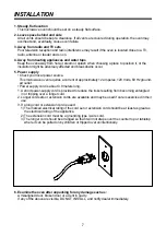
Страница 8: ...proximately 12 amperes 120 Volts 60 Hz ground ed outlet Power supply cord is about 0 8 meters long 1 A short power supply cord is provided to reduce the risks resulting from becoming entangled in or tripping over a longer cord 2 Longer cord sets or extension cords are available and may be used if care is exercised in their use 3 If a long cord or extension cord is used 1 The marked electrical rati...

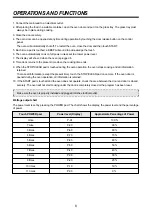
Страница 9: ...OP CLEAR pad is touched during the oven operation the oven stops cooking and all information retained To erase all information except the present time touch the STOP CLEAR pad once more If the oven door is opened during the oven operation all information is retained 10 If the START pad is touched and the oven does not operate check the area between the door and door is closed securely The oven wil...

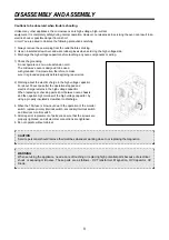
Страница 10: ...nning repair work 2 Warning about the electric charge in the high voltage capacitor For about 30 seconds after the operation stopped and electric charge remains in the high voltage capacitor When replacing or checking parts short between oven chassis and the negative high terminal of the high voltage capacitor by using a properly insulated screwdriver to discharge 4 When the 15A fuse is blown out ...

Страница 11: ...rd 2 To remove door assembly 1 Remove two screws which secure the stopper hinge top 2 Remove the door assembly from top plate of cavity 3 Reverse the above for reassembly NOTE After replacing the door assembly perform a check o f correct a lignment with the hinge and cavity front p late ...

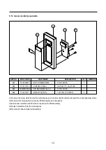
Страница 12: ...EN O GLASS T3 2 1 3517005360 GLASS T3 2 MIRROR 1 KOR 164H9A27 A08 3512203930 FRAME DOOR ABS SG 175 SG 0760D 1 A09 7122402011 SCREW TAPPING T2S TRS 4X20 MFZN 2 A10 3512603630 HANDLE DOOR KOR 164H0A 1 A04 A05 A02 A06 A01 A03 A08 A07 A09 A10 1 Remove the gasket door A01 from door plate 2 Remove the door frame A08 from door plate 3 Remove two screws A09 from door plate 4 Remove the stopper hinge top A...

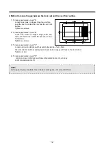
Страница 13: ...p located on part C Loosen a screw on interlock switch assembly located top of oven body Draw the interlock switch assembly inward as possible to engage with hook on the door bottom Tighten a screw 4 To reduce gap located on part D Loosen a screw on interlock switch assembly located bottom of oven body and 4 are same as step 3 1 2 3 4 5 6 7 8 9 0 KICHEN TIMER CLOCK POWER STOP CLEAR START SPEEDY CO...

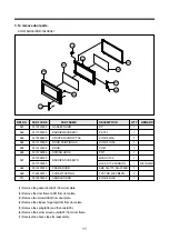
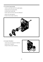
Страница 14: ...il from the connector of the PCB assembly 4 Detach membrane from the control panel 5 Reverse the above steps for reassembly 5 To remove control panel parts B01 B02 B03 B04 REF NO PART CODE PART NAME DESCRIPTION Q TY REMARK B01 3518520890 SWITCH MEMBRANE KOR 164H0A 1 B02 3516719140 CONTROL PANEL ABS SG 175 SG 0760D 1 B03 PKMPMSKN00 PCB MAIN MANUAL AS KOR 161H0A 1 B04 7112401211 SCREW TAPPING T2S TR...

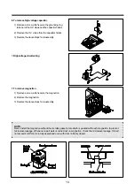
Страница 15: ...age circuit wiring 7 To remove magnetron 1 Remove a screw which secure the magnetron 2 Remove the magnetron 3 Reverse the above steps for reassembly NOTE Never install the magnetron without the metallic gasket p late which is packed with each magnetron to prevent microwave leakage Whenever repair work is carried out on magnetron check the microwave leakage It shall not exceed 4mW cm2 for a fully a...

Страница 16: ... assembly 3 Pull the fan from the motor shaft 4 Remove two screws which secure the motor shaded pole 5 Remove the motor shaded pole 6 Reverse the above steps for reassembly 9 To remove H V transformer 1 Remove four screws holding the H V transformer 2 Remove the H V transformer 3 Reverse the above steps for reassembly ...

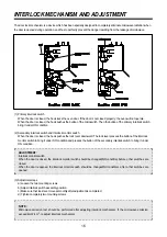
Страница 17: ... pushes the lock lever downward The lock lever presses the button of the interlock monitor switch to bring it under NO condition and presses the button of the secondary interlock switch to bring it under ON condition 3 Adjustment steps a Loosen the two mounting screws b Adjust interlock switch assembly position c Make sure that lock lever moves smoothly after adjustment is completed d Tighten comp...

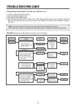
Страница 18: ...onnected of the terminals and power cord before check the parts listed below CHECK RESULT CAUSE REMEDY Fuse blows Continuity No Continuity Continuity 0 i nfinite or Approx 150 310 normal Replace NOTE 1 Replace NOTE 1 Replace Replace Check continuity of primary winding of low voltage transformer Malfunction of interlock monitor switch Defective low voltage transformer Check continuity of interlock ...

Страница 19: ...ity Normal Defective touch control circuit Open power supply cord Malfunction of secondary interlock switch Replace Check continuity of power supply cord Replace Replace CONDITION CHECK RESULT CAUSE REMEDY Turn table motor and oven lamp do not turn on No Continuity Check continuity of primary interlock switch Check continuity of secondary interlock switch Check D C voltage being supplied to RELAY ...

Страница 20: ...tacts of RELAY RY1 or open relay coil REMEDY Replace Replace Replace Replace Replace Replace Replace Replace No microwave oscillation Check continuity of high voltage rectifier in forward and backward direction with DC megger Check continuity of high voltage capacitor terminals with wires removed Connect megger leads to magnetron terminal and magnetron body Check resistance of primary and secondar...

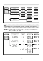
Страница 21: ...ime of day when clear pad is touched 11 Oven lamp and turntable motor do not stop although cooking is finished Check if the RELAY 2 contacts close if they are close replace touch control circuit 20 TROUBLE 4 The following visual conditions indicate a probable defective touch control circuit or membrane switch assembly NOTE Before following the particular steps listed above in the trouble shooting ...

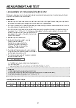
Страница 22: ...ssel the load is immedi ately placed on the center of the shelf which is in the lowest normal position 4 Microwave power is switched on 5 Heating time should be exactly A seconds Refer to table as following Heating time is measured while the microwave generator is operating at full power The filament heat up time for magnetron is not included 6 The initial and final temperature of water is selecte...

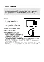
Страница 23: ...abinet door seem door viewing screen the exhaust air vents and the suction air vents 3 Measuring should be in a counter clockwise direction at a rate of 1 in sec If the leakage of the cabinet door seem is unknown move the probe more slowly 4 When measuring near a corner of the door keep the probe perpendicular to the areas making sure the probe end at the base of the cone does not get closer than ...

Страница 24: ...ter set on the highest resistance scale measure the resistance across the diode terminals Reverse the meter leads and again observe the resistance reading Meter with 6V 9V or higher voltage batter ies should be used to check the front back resistance of the diode otherwise an infinite resistance may be read in both directions A normal diode s resistance will be infinite in one direction and severa...

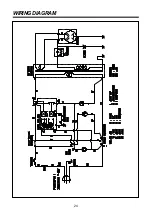
Страница 25: ...24 WIRING DIAGRAM ...

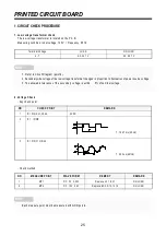
Страница 26: ... IC1 PIN 2 21 30 34 5VDC 2 IC1 P IN 35 T 16 67 ms 60Hz 3 IC1 PIN 31 OR 32 T 250 ns 4MHz NO MEASURE POINT WAVE FORM REMEDY REMARK 1 MP1 DC 5V 0 25V Replace VL1 EC1 NO LOAD 2 MP2 DC 12V 2 0V Replace EC2 D12 13 14 NO LOAD NOTE 1 Refer to Circuit Diagram point 4 2 Secondary side voltage of the low voltage transformer changes in proportion to fluctuation of power source voltage 3 The allowable toleranc...

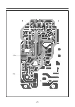
Страница 27: ...26 ...

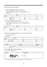
Страница 28: ... the door is opened during operation the count down timer does not stop refer to Circuit Diagram Point 1 Check method 5 When the digital clock does not operate properly refer to Circuit Diagram Point 5 If clock does not keep exact time you must check resistor R15 16 zener diodeZD1 POINT STATE A B RELAY 2 ON 5VDC GND RELAY 2 OFF GND 12VDC POINT STATE A B RELAY 1 ON 5VDC GND RELAY 1 OFF GND 12VDC PO...

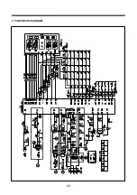
Страница 29: ...28 2 PCB CIRCUIT DIAGRAM ...

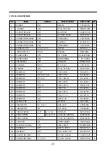
Страница 30: ...R R8 10 12 14 22 1 6W 1K 5 RD AZ102J 5 17 RESISTOR R11 20 21 1 6W 100K 5 RD AZ104J 3 18 RESISTOR R13 1 6W 200 5 RD AZ201J 1 19 RESISTOR R15 16 1 6W 10K 5 RD AZ 103J 2 20 RESISTOR R17 1 6W 510J RD AZ511J 1 21 RESISTOR R18 1 6W 1M 5 RD AZ105J 1 22 RESISTOR R19 1 4W 5 1 5 RD 4Z510J 1 23 RESISTOR R23 1 6W 4 7KJ RD AZ472J 1 24 REGULATOR VL1 MC7905C 1MC7905C 1 25 TRANSISTOR Q1 5 9 11 KRA 102M TZRA102M 8...

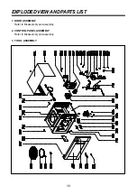
Страница 31: ...30 EXPLODED VIEW AND PARTS LIST 1 DOOR ASSEMBLY Refer to Disassembly and assembly 2 CONTROL PANEL ASSEMBLY Refer to Disassembly and assembly 3 TOTAL ASSEMBLY ...
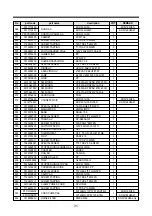
Страница 32: ...4H9A27 F20 3516003800 SPECIAL SCREW T2 FLANGE 5 8 MFZN 1 F21 3518002900 MAGNETRON 2M218J MF P 1 F22 3510311800 BASE SBHG T0 8 1 F23 3516003700 SPECIAL SCREW TT3 HEX 4 9 FLG MFZN 4 F24 3518113800 TRANS HV DY N95A0 16T 1 F25 7121400611 SCREW TAPPING T2S PAN 4 6 MFZN 1 F26 3966820200 MOTOR SYNCRO 120V 2W GM 16 12F17 1 F27 3513003400 HOLDER THERMOSTAT PBT 1 F28 3518905300 THERMOSTAT OFF 75 ON 65 H 187...

Страница 33: ...S M NO R637R0S001 DAEWOO ELECTRONICS CORP 686 AHYEON DONG MAPO GU SEOUL KOREA C P O BOX 8003 SEOUL KOREA TELEX DWELEC K28177 8 CABLE DAEWOOELEC PRINTED DATE Apr 2007 ...

Отзывы: