


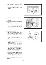

(6) Set the constant voltage power sup-
ply at 24 V.
(7) Turn on the digital voltmeter’s power
switch.
- 126 -
EA2M4015
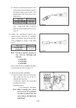
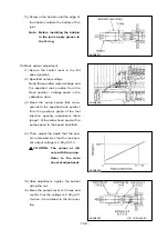
(8) Turn the checker’s power ON.
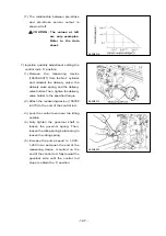
(9) Trun the ‘Normal-Act Off’ switch to
‘Normal’
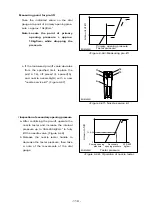
(10) Turn the target dial until the fuel stops
flowing.
If the pre-stroke sensor output is not
2.62
L
0.01 V, turn the pre-stroke actu-
ator in a counterclockwise direction
(viewed from the drive side) until
2.62
L
0.01 V is obtained.
EA2M4016
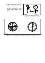
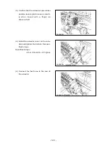
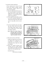
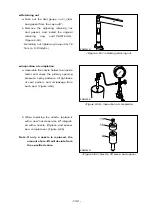
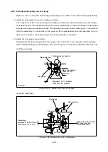
6) Installation confirmation
(1) Set the control unit’s power switch
OFF to cut the power to the actuator.
(2) Turn the pump test stand’s flywheel
and confirm that the pre-stroke is
6.4
L
0.03mm(refer to pages 51 and
52).
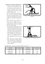
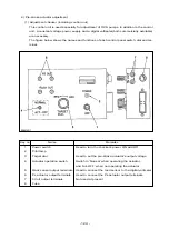
(3) Turn the checker’s power switch on
and then turn the ‘Normal-Act OFF’
switch to ‘Act-OFF’.
At this time confirm that the pre-
stroke sensor output is 1.2
L
0.2 V
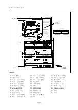
(4) Set the control unit’s ‘Normal-Act
OFF’ switch to ‘Normal’, and position
each switch, etc, as shown at left.
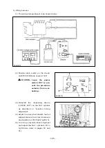
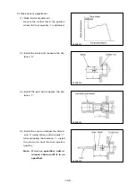
(5) Turn the rarget dial, and adjust the
rack sensor output to 3-0.02 V.
(6) Turn the pump test stand’s flywheel
and confirm that the No.1 cylinder’s
pre-stroke does not exceed 3.4mm.
If the above results cannot be obtained,
repeat all procedures from ‘Timing rod
assembly.
EA2M4017


